Operation
This section describes the system composition for the evaluation of the OPTIGA™ Authenticate NBT with the static connection handover example applications (during operation). It provides the design details and the core methodology used in the example applications for this use case.
To enable the OPTIGA™ Authenticate NBT for this use cases, it first needs to be configured accordingly (see Personalization for details). After personalization, an Android mobile phone (iOS not supported as of 07/25) reads the connection handover record from the device’s NDEF message to establish a Bluetooth® connection to the host MCU board.
System architecture
For static connection handover, the OPTIGA™ Authenticate NBT utilizes its NDEF message to store the connection information of an alternative communication channel (e.g., Bluetooth). The mobile phone app reads this information via NFC and establishes a connection to the host MCU board. The used hardware and software components for this use case will be covered in detail below.
Hardware
For the demonstration of the use case, an Android mobile phone and the OPTIGA™ Authenticate NBT Development Kit are needed. The development shield needs to be attached to the pre-soldered pin sockets of the host MCU board. This connects the power supply (3V3, GND) and the I2C pins (SDA, SCL). Even tough the IRQ pin is connected, it is not actively utilized in this use case’s example applications.
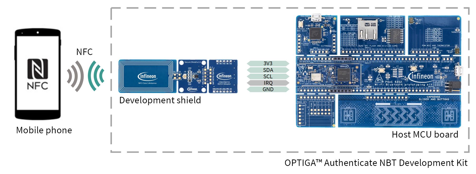
Fig. 108 Hardware components for operation.
Software
The involved software divides into the application(s) running on the OPTIGA™ Authenticate NBT and the embedded application (running on the host MCU PSOC™ board). No dedicated app is required on Android mobile phones, as the OS is already capable of reading and interpreting connection handover when tapping NFC devices. The following figure shows an overview of the involved software components:
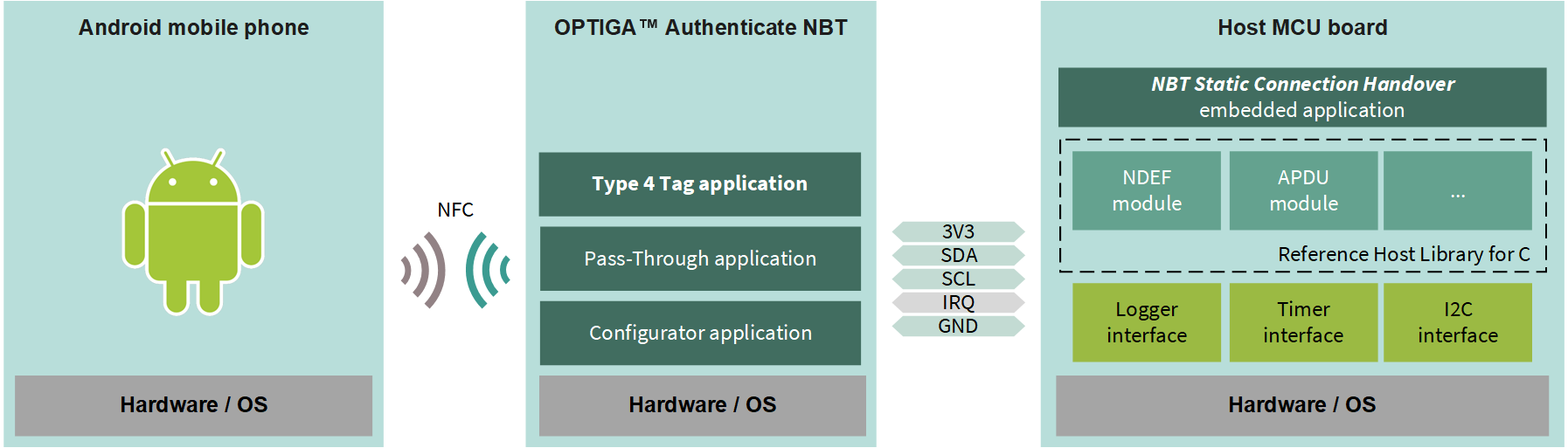
Fig. 109 Software architecture of the included applications for the operational use case.
The embedded application is provided as source code via GitHub (see Software requirements). It is considered off-chip software, which means it can be modified and recompiled.
In contrast, the NBT applications are considered on-chip software, pre-flashed on the device and not alterable. The operational flow utilizes only the Type 4 Tag application of the OPTIGA™ Authenticate NBT’s on-chip applications. Refer to the extended datasheet for more information about the on-chip applications.
Operational flow
The example implementation of this use case involves the handover of the Bluetooth® connection information from the host MCU board to a mobile phone via NFC. The application flow of reading the connection handover record as well as design details can be found below.
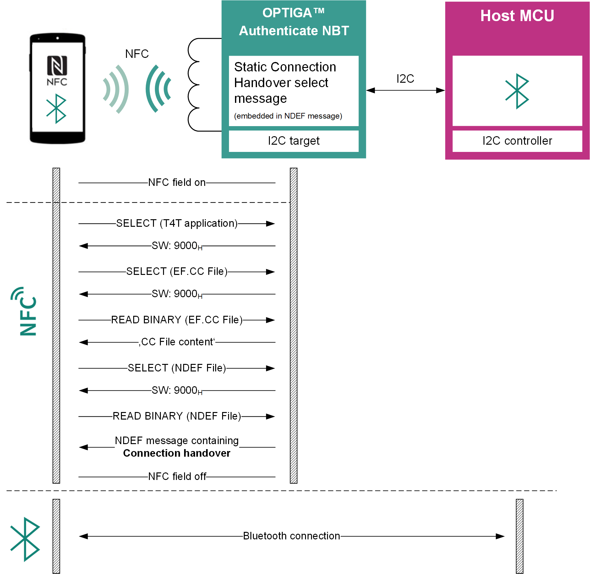
Fig. 110 Connection handover flow.
Design details
Describes the core design principles used for the implementation of the applications to demonstrate this use case. Additionally, cross-application definitions are stated here.
Bluetooth® simple pairing record
During startup, the MCU application writes a Bluetooth® simple pairing record to the OPTIGA™ Authenticate NBT’s NDEF message. This record contains the Bluetooth® connection information of the host MCU board, which can be read by the mobile phone app when tapping the OPTIGA™ Authenticate NBT.
The basic structure of the Bluetooth® simple pairing record can be found in the OPTIGA™ Authenticate NBT Static Connection Handover Use Case Guide.
There exists a dedicated specification for Bluetooth® Secure Simple Pairing from the NFC Forum, which is available at NFC Forum website.
The NDEF message is structured as follows:
static uint8_t CONNECTION_HANDOVER_MESSAGE[] = {
   // NDEF message length
   0x00U, 0x23U + 0x4EU,
   // NDEF Record Header
   0xD2U,
   // Record Type Length
   0x20U,
   // Payload Length
   0x4EU,
   // Record Type Name: application/vnd.bluetooth.le.oob
   0x61U, 0x70U, 0x70U, 0x6CU, 0x69U, 0x63U, 0x61U, 0x74U, 0x69U, 0x6FU, 0x6EU, 0x2FU, 0x76U, 0x6EU, 0x64U, 0x2EU,
   0x62U, 0x6CU, 0x75U, 0x65U, 0x74U, 0x6FU, 0x6FU, 0x74U, 0x68U, 0x2EU, 0x6CU, 0x65U, 0x2EU, 0x6FU, 0x6FU, 0x62U,
   // Payload
   // BLE Device Address (1B length, 1B data type, 6B address, 1B address type)
   0x08U, 0x1BU, 0xFFU, 0xFFU, 0xFFU, 0xFFU, 0xFFU, 0XFFU, 0x00U,
   // BLE Role (1B length, 1B data type, 1B role "Peripheral")
   0x02U, 0x1CU, 0x00U,
   // BLE Local Name (1B length, 1B data type, 3B name "NBT")
   0x04U, 0x09U, 0x4EU, 0x42U, 0x54U,
   // Appearance (1B length, 1B data type, 2B appearance "HID: Mouse")
   0x03U, 0x19U, 0xC2U, 0x03U,
   // Security Manager TK (1B length, 1B data type, 16B key)
   0x11U, 0x10U, 0x00U, 0x00U, 0x00U, 0x00U, 0x00U, 0x00U, 0x00U, 0x00U, 0x00U, 0x00U, 0x00U, 0x00U, 0x00U, 0x00U, 0x00U, 0x00U,
   // LE Secure Connection Confirmation Value (1B length, 1B data type, 16B confirmation value)
   0x11U, 0x22U, 0xFFU, 0xFFU, 0xFFU, 0xFFU, 0xFFU, 0xFFU, 0xFFU, 0xFFU, 0xFFU, 0xFFU, 0xFFU, 0xFFU, 0xFFU, 0xFFU, 0xFFU, 0xFFU,
   // LE Secure Connection Random Value (1B length, 1B data type, 16B random value)
   0x11U, 0x23U, 0xFFU, 0xFFU, 0xFFU, 0xFFU, 0xFFU, 0xFFU, 0xFFU, 0xFFU, 0xFFU, 0xFFU, 0xFFU, 0xFFU, 0xFFU, 0xFFU, 0xFFU, 0xFFU,
   // LE OOB Flags (1B length, 1B data type, 1B flags LE General Discoverable Mode, BR/EDR not supported
   0x02U, 0x01U, 0x06U
};
The following fields are changed according to the host MCU board’s Bluetooth® connection information:
BLE Device Address: The Bluetooth® address of the host MCU board. - Updated by the embedded application during startup once the BLE MAC address is available
LE Secure Connection Confirmation Value: The confirmation value for secure connections. - Updated by the embedded application during startup once the secure connection confirmation value is available
LE Secure Connection Random Value: The random value for secure connections. - Updated by the embedded application during startup once the secure connection random value is available
Pin mapping
Development shield |
MCU |
Function |
|---|---|---|
SDA |
P6.1 (CYBSP_I2C_SDA) |
I2C data |
SCL |
P6.0 (CYBSP_I2C_SCL) |
I2C clock |
IRQ |
P6.2 |
Interrupt |
3V3 |
VDD |
Power and pad supply (3V3) |
GND |
GND |
Common ground reference |