Step-by-step guide
This guide shows the single steps to perform an evaluation of the OPTIGA™ Authenticate NBT in the pass-through use case. The scope is the evaluation of the OPTIGA™ Authenticate NBT Development Kit with an Android-based mobile phone.
Prerequisites
The following components have to be available to perform the evaluation:
Android-based mobile phone (Android 11+)
Windows-based development PC
Setting up the software
To set up the applications for the evaluation of the PT use case, the following software is required:
UART terminal (eg. Tera Term)
In addition, the board needs to be programmed. To make sure everything runs smoothly, follow the provided installation guide below in order.
ModusToolbox™
Download and install ModusToolbox™ from the official website. Follow the installation wizard’s prompts to complete the installation.
Note
ModusToolbox™ 3.4 was used for this guide.
Open the ModusToolbox™ Setup and under Base Packages select ModusToolbox™ Tools Package and Eclipse IDE for ModusToolbox™ and under Additional Packages select ModusToolbox™ Programming tools. Click “Next” and follow the installation prompts.
Importing the example application
The OPTIGA™ Authenticate NBT PT Application for ModusToolbox™ is directly available as a template application in ModusToolbox™. There is no need to manually clone the Git repository to your local hard drive, since this is implicitly handled by ModusToolbox™.
Launch the Eclipse IDE for ModusToolbox™ (e.g., via the Windows Start Menu)
(optional) Create a new workspace
Create a new project:
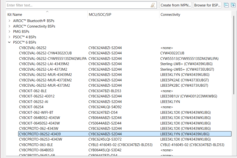
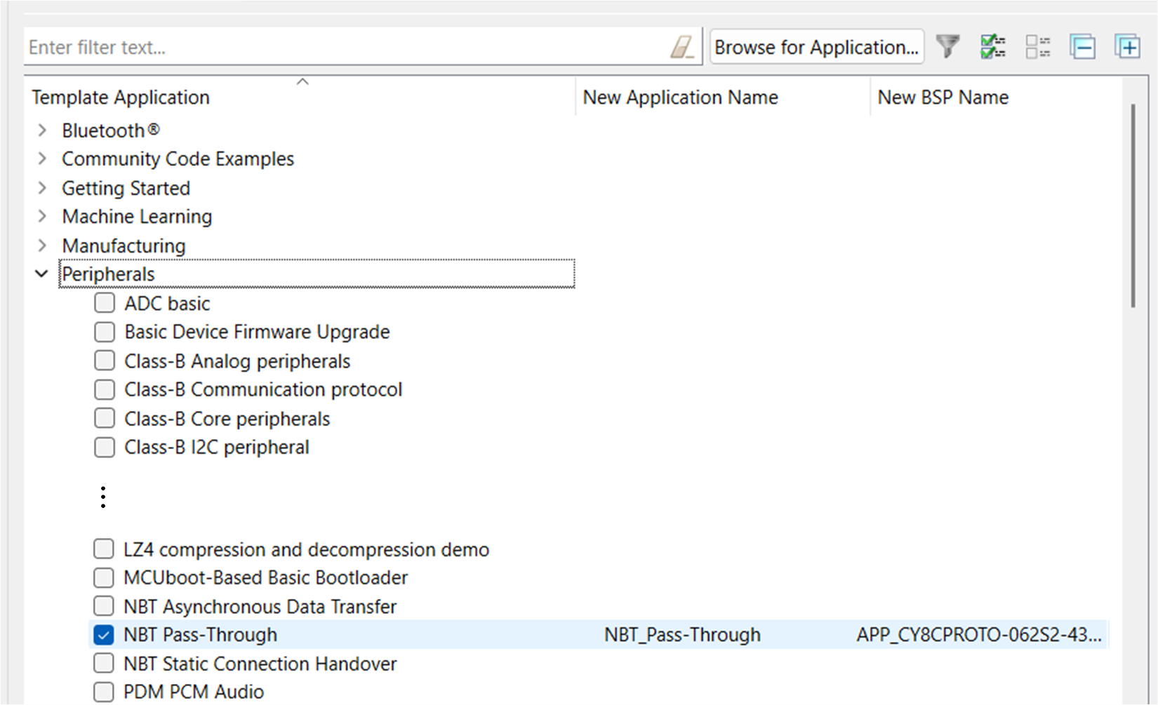
Flashing the application to the board
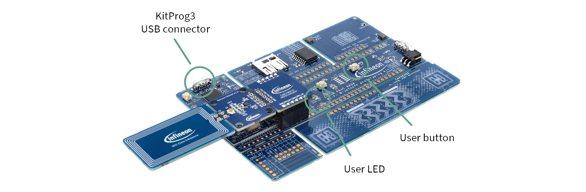
Fig. 97 The OPTIGA™ Authenticate NBT Development Kit.
Attach the shield to the host MCU board, as shown above (Fig. 97)
Connect the board to your PC using the provided USB cable through the KitProg3 USB connector
In the Eclipse IDE for ModusToolbox™, select the application project in the Project Explorer. Then in the Quick Panel, scroll down, and under Launches click NBT_Pass-Through Program (KitProg3_MiniProg4) and wait for it to build.
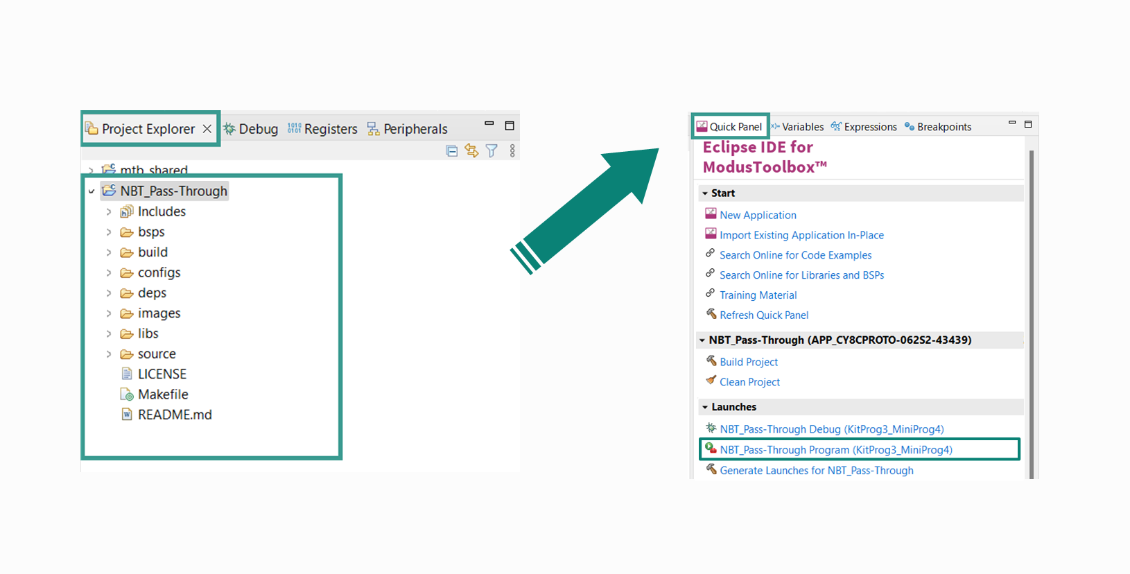
Fig. 98 Flashing the application in ModusToolbox.
Note
If you are unsure about the assembly of the hardware components, please consult the ‘Quick Start Guide’ included with the OPTIGA™ Authenticate NBT Development Kit
Android Studio
Set up the NBT Pass-Through mobile phone app using Android Studio and
install it to the mobile phone (see installation instructions in
NBT Personalization step-by-step guide). Be
aware that the URL needs to be changed to https://github.com/Infineon/optiga-nbt-example-pt-android.
UART terminal
A UART terminal (or terminal emulator) needs to be installed. Go to the Tera Term website and look for the latest release under Download. It will redirect you to GitHub where you can download the executable under Assets. Follow the installation wizard’s prompts to complete the installation.
Note
Tera Term 5.3 was used for this guide.
Setting up the UART terminal
Connect the development kit’s host MCU board to the PC via USB (KitProg3 USB connector)
Start Tera Term, set the connection type to Serial and select the KitProg3 USB-UART
Under
Setup -> Serial portchange Speed to 115200 and press New setting
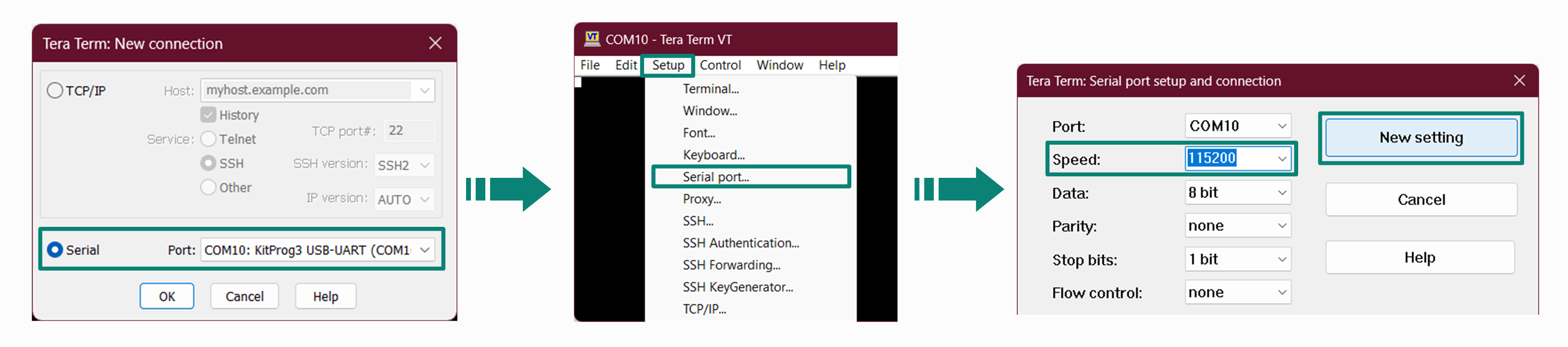
Fig. 99 Connecting Tera Term to the development kit.
After powering/resetting the development kit, the embedded application starts automatically and prints its logs to the UART terminal.
Evaluation of the use case
After following the above steps, the mobile phone and the development kit should be ready for evaluation.
Setup
The main configuration for this use case is the bridge tag setup (for personalization and operation). The NBT needs to be connected to a host MCU via I2C. So the shield has to be plugged into the development kit’s host MCU board.
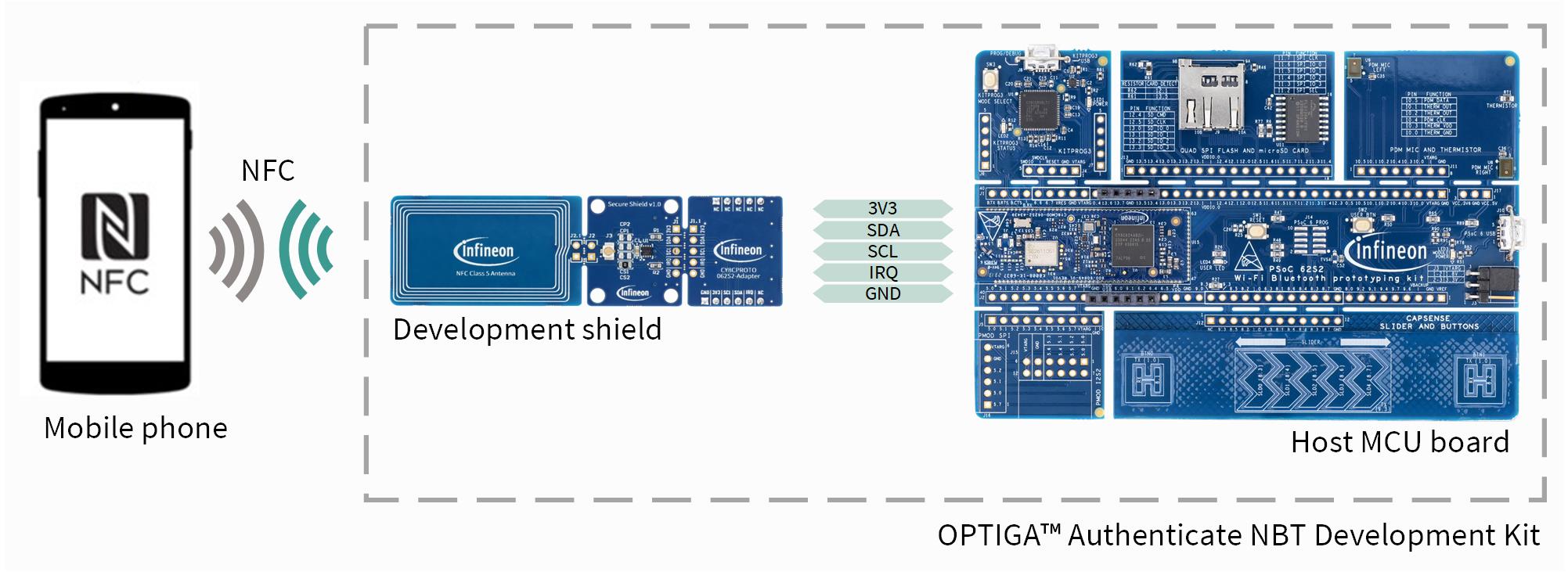
Fig. 100 Hardware setup for evaluation of this use case.
The mobile phone needs to have the NBT Pass-Through mobile phone app installed.
Personalization
The personalization of the OPTIGA™ Authenticate NBT is implicitly done during the startup of the embedded application via I2C. Thus, there are no additional steps required to personalize the NBT for the PT use case.
Controlling the LED state
This section describes the operational part of the evaluation.
Prerequisites
Power the development kit (eg. via PC connection or charger).
(optional) Connect the UART terminal for debugging
Launch the embedded application
The embedded application is automatically started directly after programming the board. If you want to restart it, you can do so by pressing the Reset button on the development kit (or power cycle it).
Launch the NBT Pass-Through mobile phone app
Setting the LED state
Use the light bulb to set the desired LED state (Enabled/Disabled)
Then physically tab the mobile phone to the development kit’s NFC antenna (eg. the attached shield), as described in the app’s GUI
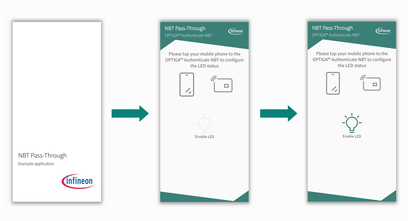
Fig. 101 NBT Pass-Through mobile phone app user interface.
Confirm that the LED state is updated accordingly on the board[*]. In the app’s GUI, it should state that the LED state has been set.
Observe/Confirm the logged data on the UART terminal as seen in the screenshot below:
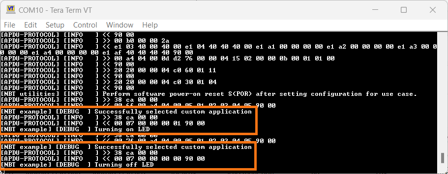
Fig. 102 The UART terminal output when setting the LED state.