MTB CAT1 Peripheral driver library
ADCMic (Delta-Sigma ADC with PDM microphone support)

General Description

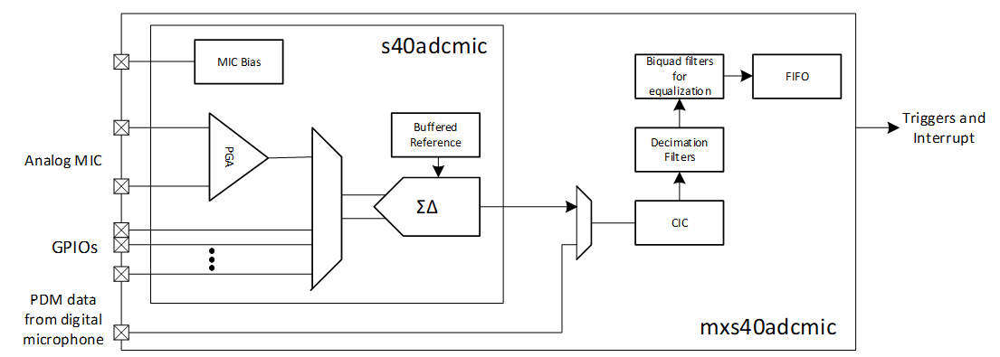
ADCMic driver is used to process analog and digital microphone signal and DC signal with the mxs40adcmic IP.

This IP interfaces with Delta-Sigma modulator part of the s40adcmic and implements CIC, decimation (FIR) and biquad filters. The ADC result is read by the CPU or the DMA from the FIFO of mxs40adcmic (and from CIC register for DC measurement). Instead of taking modulator data from s40adcmic, mxs40adcmic can also be configured to take PDM input directly from an external digital microphone.

ADCMicBlockDiagram.png

Consult the datasheet of your device for details of the clocking system.

The high level features of the subsystem are:

Usage

The high level steps to use this driver are:

  1. Initialization and Enabling
  2. Clocks
  3. Triggering
  4. Timer
  5. Handling Interrupts
  6. DC Voltage Measurement Accuracy
  7. FIFO Usage

Initialization and Enabling

To configure the ADCMic subsystem call Cy_ADCMic_Init. Pass in a pointer to the MXS40ADCMIC_Type structure for the base hardware register address, pass in the configuration structure cy_stc_adcmic_config_t, and pass in the operation mode.

After initialization, call Cy_ADCMic_Enable to enable the block.

The configuration can be defined as follows:

{
.micBiasLz = false,
.micClamp = false,
.pgaGain = CY_ADCMIC_PGA_GAIN_6, /* 2X */
.pgaInCm = CY_ADCMIC_INCM_0_4,
.pgaOutCm = CY_ADCMIC_OUTCM_0_6,
.biQuadConfig = NULL,
.fifoTrigger = true,
.fifoFull = 4, /* (64 - 4) * 2 = 120 samples */
.fifoEmpty = 4
};
/* The structure which will not be reconfŃ–gured can be declared as const */
const cy_stc_adcmic_pdm_config_t pdmConfig =
{
.clockInv = false,
.latchDelay = 1,
.biQuadConfig = NULL,
.fifoTrigger = true,
.fifoFull = 4, /* (64 - 4) * 2 = 120 samples */
.fifoEmpty = 4
};
{
.channel = CY_ADCMIC_GPIO7,
.timerPeriod = 3000, /* ~ 30 uS @clk_sys = 96MHz */
.context = &context
};
const cy_stc_adcmic_config_t config =
{
.micConfig = &micConfig,
/* In case of the mode structure is declared as const - an additional type cast is needed here: */
.pdmConfig = (cy_stc_adcmic_pdm_config_t *)&pdmConfig,
.dcConfig = &dcConfig,
};

Analog Microphone (MIC) Mode

/* Scenario: Initialize ADCMic for the analog microphone operation: */
if (CY_ADCMIC_SUCCESS != Cy_ADCMic_Init(MXS40ADCMIC0, &config, CY_ADCMIC_MIC))
{
/* Something went wrong, insert error handling here */
}
{
/* Something went wrong, insert error handling here */
}
Cy_ADCMic_Enable(MXS40ADCMIC0); /* Enable the block operation */

Usually the MIC mode is used with FIFO, see FIFO Usage

Digital Microphone (PDM) Mode

/* Scenario: Initialize ADCMic for the digital microphone operation: */
if (CY_ADCMIC_SUCCESS != Cy_ADCMic_Init(MXS40ADCMIC0, &config, CY_ADCMIC_PDM))
{
/* Something went wrong, insert error handling here */
}
Cy_ADCMic_Enable(MXS40ADCMIC0); /* Enable the block operation */

Usually the MIC mode is used with FIFO, see FIFO Usage

DC Measurement (DC) Mode

/* Scenario: Initialize ADCMic for the DC measurement: */
uint16_t data = 0U;
if (CY_ADCMIC_SUCCESS != Cy_ADCMic_Init(MXS40ADCMIC0, &config, CY_ADCMIC_DC))
{
/* Something went wrong, insert error handling here */
}
Cy_ADCMic_SelectDcChannel(MXS40ADCMIC0, CY_ADCMIC_GPIO0); /* Switch to the GPIO_0 */
Cy_ADCMic_Enable(MXS40ADCMIC0); /* Enable the block operation */
Cy_ADCMic_IsEndConversion(MXS40ADCMIC0, CY_ADCMIC_WAIT_FOR_RESULT); /* Wait the conversion is done */
Cy_ADCMic_Disable(MXS40ADCMIC0); /* Stop the operation */
data = Cy_ADCMic_GetDcResult(MXS40ADCMIC0); /* Get the result */

Biquad filter Initialization

The biquad filter usually is used to the audio stream equalization (in MIC or PDM modes):

{
.bq0_num1_coeff = 0x3F27UL,
.bq0_num2_coeff = 0x81B2UL,
.bq0_num3_coeff = 0x3F27UL,
.bq0_den2_coeff = 0x81B5UL,
.bq0_den3_coeff = 0x3E51UL,
.bq1_num1_coeff = 0x4CCFUL,
.bq1_num2_coeff = 0UL,
.bq1_num3_coeff = 0UL,
.bq1_den2_coeff = 0UL,
.bq1_den3_coeff = 0UL,
.bq2_num1_coeff = 0x4000UL,
.bq2_num2_coeff = 0UL,
.bq2_num3_coeff = 0UL,
.bq2_den2_coeff = 0UL,
.bq2_den3_coeff = 0UL,
.bq3_num1_coeff = 0x4000UL,
.bq3_num2_coeff = 0UL,
.bq3_num3_coeff = 0UL,
.bq3_den2_coeff = 0UL,
.bq3_den3_coeff = 0UL,
.bq4_num1_coeff = 0x4000UL,
.bq4_num2_coeff = 0UL,
.bq4_num3_coeff = 0UL,
.bq4_den2_coeff = 0UL,
.bq4_den3_coeff = 0UL,
};
/* Scenario: Initialize entire ADCMic with biquad filter */
config.micConfig->biQuadConfig = &biquadCfg;
if (CY_ADCMIC_SUCCESS != Cy_ADCMic_Init(MXS40ADCMIC0, &config, CY_ADCMIC_MIC))
{
/* Something went wrong, insert error handling here */
}
/* or initialize the BiQuad filter separately */
Cy_ADCMic_InitBiquad(MXS40ADCMIC0, &biquadCfg);
Cy_ADCMic_BiquadBypass(MXS40ADCMIC0, false); /* Unbypass the biquad filter */

Clocks

The ADCMic requires two input clocks:

For more exact information on the ADCMic clock routing, refer to the datasheet for your device.

Triggering

The ADCMic subsystem has two output triggers: from the timer and from the FIFO, the timer generates trigger always if enabled, the FIFO trigger could be configured separately for MIC and PDM modes by the cy_stc_adcmic_mic_config_t::fifoTrigger and cy_stc_adcmic_pdm_config_t::fifoTrigger respectively.

Also, they could be routed to any periphery using TrigMux (Trigger Multiplexer) driver, e.g. to DW block:

/* Scenario: route the ADCMic FIFO trigger to the DW0 block */
Cy_TrigMux_Connect(TRIG_IN_MUX_4_ADCMIC_DATA_AVAIL, TRIG_OUT_MUX_0_PDMA0_TR_IN0, false, TRIGGER_TYPE_LEVEL);

Timer

The Timer is used for DC measurement for two purposes:

The timer period and input signal source are configured by the cy_stc_adcmic_dc_config_t::timerPeriod and cy_stc_adcmic_dc_config_t::timerInput fields correspondingly.

Handling Interrupts

The ADCMic subsystem has two interrupt sources: the timer and the FIFO. The FIFO interrupt can have several reasons, see FIFO Status Masks

The ADCMic interrupt to the NVIC is raised any time the intersection (logic and) of the interrupt flags and the corresponding interrupt masks are non-zero.

Implement an interrupt routine and assign it to the ADCMic interrupt. Use the pre-defined enumeration, adcmic_interrupt_adcmic_IRQn, as the interrupt source for the ADCMic.

The following code snippet demonstrates how to implement a routine to handle the interrupt. The routine gets called when any one of the ADCMic interrupts are triggered. When servicing an interrupt, the user must clear the interrupt so that subsequent interrupts can be handled.

The following code snippet demonstrates how to configure and enable the interrupt.

/* ISR function to handle ADCMic interrupts.
* This same routine gets called when any of the enabled ADCMic interrupt sources are enabled.
*/
uint16_t data[64];
uint8_t dataCount;
void ADCMic_Isr(void)
{
/* Read interrupt status register. */
uint32_t intrStatus = Cy_ADCMic_GetInterruptStatusMasked(MXS40ADCMIC0);
/* Check what triggered the interrupt. */
if (0UL != (CY_ADCMIC_INTR_DATA & intrStatus))
{
if (0U != (CY_ADCMIC_FIFO_EMPTY & Cy_ADCMic_GetFifoStatus(MXS40ADCMIC0)))
{
dataCount = Cy_ADCMic_ReadFifoAll(MXS40ADCMIC0, data);
}
}
/* Check also the DC interrupt status, if enabled. */
/* Clear the handled interrupt. */
Cy_ADCMic_ClearInterrupt(MXS40ADCMIC0, intrStatus);
}
/* Scenario: Configure and enable the ADCMic interrupt. */
const cy_stc_sysint_t ADCMic_IRQ_cfg =
{
.intrSrc = adcmic_interrupt_adcmic_IRQn, /* Interrupt source is the ADCMic interrupt */
.intrPriority = 7UL /* Interrupt priority is 7 */
};
/* Configure the interrupt with vector at ADCMic_Isr(). */
(void)Cy_SysInt_Init(&ADCMic_IRQ_cfg, ADCMic_Isr);
/* Enable the interrupt. */
NVIC_EnableIRQ(ADCMic_IRQ_cfg.intrSrc);
/* Clear possible interrupt erroneously raised during block enabling */

Alternately, instead of handling the interrupts, the Cy_ADCMic_IsEndConversion function allows for firmware polling of the end of DC conversion status.

FIFO Usage

The ADCMic subsystem in the MIC and PDM modes stores the audio data into the FIFO. It can be configured separately for the MIC and PDM modes using cy_stc_adcmic_mic_config_t::fifoFull, cy_stc_adcmic_mic_config_t::fifoEmpty and cy_stc_adcmic_pdm_config_t::fifoFull, cy_stc_adcmic_pdm_config_t::fifoEmpty respectively and served either by ISR:

/* ISR function to handle ADCMic interrupts.
* This same routine gets called when any of the enabled ADCMic interrupt sources are enabled.
*/
uint16_t data[64];
uint8_t dataCount;
void ADCMic_Isr(void)
{
/* Read interrupt status register. */
uint32_t intrStatus = Cy_ADCMic_GetInterruptStatusMasked(MXS40ADCMIC0);
/* Check what triggered the interrupt. */
if (0UL != (CY_ADCMIC_INTR_DATA & intrStatus))
{
if (0U != (CY_ADCMIC_FIFO_EMPTY & Cy_ADCMic_GetFifoStatus(MXS40ADCMIC0)))
{
dataCount = Cy_ADCMic_ReadFifoAll(MXS40ADCMIC0, data);
}
}
/* Check also the DC interrupt status, if enabled. */
/* Clear the handled interrupt. */
Cy_ADCMic_ClearInterrupt(MXS40ADCMIC0, intrStatus);
}

Or by DMA:

/* Scenario: route the ADCMic FIFO trigger to the DW0 block */
Cy_TrigMux_Connect(TRIG_IN_MUX_4_ADCMIC_DATA_AVAIL, TRIG_OUT_MUX_0_PDMA0_TR_IN0, false, TRIGGER_TYPE_LEVEL);

DC Voltage Measurement Accuracy

The default Offset CY_ADCMIC_DC_OFFSET and Gain for both ranges CY_ADCMIC_DC_1_8_GAIN and CY_ADCMIC_DC_3_6_GAIN are precalculated based on the theory of the ADCMic operation DC measurement definitions.

So basically the raw count retrieved using Cy_ADCMic_GetDcResult for the desired DC input can be directly feed into any of the Cy_ADCMic_CountsTo_Volts, Cy_ADCMic_CountsTo_mVolts, or Cy_ADCMic_CountsTo_uVolts functions and have for some extend accurate result.

However, to increase the accuracy the real ADCMic Gain and Offset can be defined by physically measuring the Reference Ground CY_ADCMIC_REFGND and the Reference BandGap CY_ADCMIC_BGREF.

For example:

/* A typical flow for the DC channel measurement using averaging to eliminate a high frequency noise */
#define AVGCNT 256
int16_t result;
int16_t offset;
int16_t gain;
int16_t GetResultAvg(cy_en_adcmic_dc_channel_t channel)
{
uint32_t i;
uint32_t avg = 0UL;
Cy_ADCMic_SelectDcChannel(MXS40ADCMIC0, channel);
Cy_ADCMic_Enable(MXS40ADCMIC0); /* Start the conversion */
Cy_ADCMic_EnableTimer(MXS40ADCMIC0);
Cy_ADCMic_IsEndConversion(MXS40ADCMIC0, CY_ADCMIC_WAIT_FOR_RESULT); /* Skip the first sample */
for (i = 0; i < AVGCNT; i++)
{
avg += (uint32_t)(int32_t)Cy_ADCMic_GetDcResult(MXS40ADCMIC0);
}
Cy_ADCMic_DisableTimer(MXS40ADCMIC0);
Cy_ADCMic_Disable(MXS40ADCMIC0); /* Stop the conversion */
return (int16_t)(int32_t)CY_SYSLIB_DIV_ROUND(avg, AVGCNT);
}
/* Then a typical flow of the Offset and Gain correction and raw counts into voltage units conversion */
uint32_t microvolts;
uint16_t millivolts;
float volts;
void Measurement(void)
{
offset = GetResultAvg(CY_ADCMIC_REFGND); /* Measure the reference GND - this is Offset value */
Cy_ADCMic_SetDcOffset(offset, &context); /* Update the Offset */
/* Measure the reference BandGap and calculate the Gain using the nominal BandGap voltage 0.85V */
gain = CY_SYSLIB_DIV_ROUND((GetResultAvg(CY_ADCMIC_BGREF) - offset) * 1000L, CY_ADCMIC_DC_VBG);
Cy_ADCMic_SetDcGain(gain, &context); /* Update the Gain */
result = GetResultAvg(CY_ADCMIC_GPIO7); /* Get the raw count of desired DC channel */
volts = Cy_ADCMic_CountsTo_Volts (result, &context); /* Convert the raw count into volts */
millivolts = Cy_ADCMic_CountsTo_mVolts(result, &context); /* Convert the raw count into millivolts */
microvolts = Cy_ADCMic_CountsTo_uVolts(result, &context); /* Convert the raw count into microvolts */
}
Note
this code snippet is not the only valid way to use this driver - it is just one possible example how it can be used.

BandGap Calibration

For further increase the measurement accuracy, the real BandGap voltage can be defined using external precise reference with exact known voltage:

Real BandGap voltage = external reference exact voltage * (BandGap counts - GND counts) / (external reference counts - GND counts).

And then use it in the Gain calculation as shown above instead of the nominal BandGap voltage CY_ADCMIC_DC_VBG.

Correlated Double Sampling

To further improve the DC measurement accuracy, the low frequency Noise could be dynamically removed by performing two measurements for each input channel sequentially: one measuring the desired DC input and the other one measuring the CY_ADCMIC_REFGND. The second measurement of theCY_ADCMIC_REFGND contains only the low frequency Noise (Flick Noise) information. It is important to perform these two measurements one after another as close as possible. The final true ADC output value is then obtained by subtracting the ADC output of the second measurement from the ADC output of the first measurement.

For example:

/* The decimator takes decades of microseconds until start to produce accurate data,
* so for the 'fast' sampling we can use up to 16x averaging - it takes a commensurate time (~32 us)
*/
#define AVGDS 16 /* Averaging rate for the double sampling */
uint32_t GetResult(cy_en_adcmic_dc_channel_t channel)
{
uint32_t i;
uint32_t avg = 0UL;
Cy_ADCMic_SelectDcChannel(MXS40ADCMIC0, channel);
Cy_ADCMic_Enable(MXS40ADCMIC0); /* Start the conversion */
Cy_ADCMic_EnableTimer(MXS40ADCMIC0);
Cy_ADCMic_IsEndConversion(MXS40ADCMIC0, CY_ADCMIC_WAIT_FOR_RESULT); /* Skip the first sample */
for (i = 0; i < AVGDS; i++)
{
avg += (uint32_t)(int32_t)Cy_ADCMic_GetDcResult(MXS40ADCMIC0);
}
Cy_ADCMic_DisableTimer(MXS40ADCMIC0);
Cy_ADCMic_Disable(MXS40ADCMIC0); /* Stop the conversion */
return avg; /* return unsigned 20-bit value */
}
int16_t GetResultDs(cy_en_adcmic_dc_channel_t channel)
{
uint32_t i;
uint32_t avg = 0UL;
uint32_t gnd = 0UL;
for (i = 0; i < AVGCNT; i++)
{
avg += GetResult(channel);
gnd += GetResult(CY_ADCMIC_REFGND);
}
offset = (int16_t)CY_SYSLIB_DIV_ROUND(gnd, AVGCNT * AVGDS); /* Calculate the Offset value */
Cy_ADCMic_SetDcOffset(offset, &context); /* Update the Offset */
if (CY_ADCMIC_BGREF == channel)
{
/* Calculate the Gain using the nominal BandGap voltage 0.85V */
gain = (int16_t)(int64_t)CY_SYSLIB_DIV_ROUND((uint64_t)(avg - gnd) * 1000L, (uint64_t)CY_ADCMIC_DC_VBG * AVGCNT * AVGDS);
Cy_ADCMic_SetDcGain(gain, &context); /* Update the Gain */
return 0; /* No need to return something meaningful */
}
else
{
return (int16_t)(int32_t)CY_SYSLIB_DIV_ROUND(avg, AVGCNT * AVGDS);
}
}
void DoubleSampling(void)
{
(void) GetResultDs(CY_ADCMIC_BGREF);
result = GetResultDs(CY_ADCMIC_GPIO7);
microvolts = Cy_ADCMic_CountsTo_uVolts(result, &context);
millivolts = Cy_ADCMic_CountsTo_mVolts(result, &context);
volts = Cy_ADCMic_CountsTo_Volts (result, &context);
}
Note
this code snippet is not the only valid way to use this driver - it is just one possible example how it can be used.

More Information

For more information on the ADCMic ADC subsystem, refer to the datasheet of your device.

Changelog

VersionChangesReason for Change
1.10 The ADCMic PDL driver ID CY_ADCMIC_ID is updated Avoiding possible driver ID collisions
1.0

The cy_en_adcmic_source_t is renamed to cy_en_adcmic_mode_t.
The CY_ADCMIC_480KSPS item is removed from the cy_en_adcmic_sample_rate_t.
The cy_en_adcmic_dc_conv_time_t is removed.
The cy_stc_adcmic_fifo_config_t is removed.
The cy_en_adcmic_dc_result_latch_mode_t is removed.
The cy_stc_adcmic_audio_analog_path_config_t is renamed to cy_stc_adcmic_mic_config_t.
The cy_stc_adcmic_audio_digital_path_config_t is renamed to cy_stc_adcmic_pdm_config_t.
The cy_stc_adcmic_dc_path_config_t is renamed to cy_stc_adcmic_dc_config_t.

The micPd parameter is removed from the cy_stc_adcmic_mic_config_t

The next parameters are added into cy_stc_adcmic_mic_config_t :

The clockDiv parameter is removed from the cy_stc_adcmic_pdm_config_t

The next parameters are added into cy_stc_adcmic_pdm_config_t :

The next parameters are removed from the cy_stc_adcmic_dc_config_t :

  • tmrLatch,
  • time.

The next parameter is renamed in the cy_stc_adcmic_dc_config_t :

The next parameters are added into cy_stc_adcmic_dc_config_t :

The next parameters are removed from the cy_stc_adcmic_config_t :

  • clockDiv,
  • source,
  • sampleRate,
  • biQuadConfig,
  • fifoConfig,
  • tmrTrgConfig.

The next parameters are renamed in the cy_stc_adcmic_config_t :

The new parameter 'mode' is added to the Cy_ADCMic_Init.
The Cy_ADCMic_Init functions if fixed to proper process the cy_stc_adcmic_mic_config_t::micClamp setting.
The Cy_ADCMic_StartConvert and Cy_ADCMic_StopConvert API functions are removed.
The Cy_ADCMic_Enable and Cy_ADCMic_Disable are updated to inherit the Start/StopConvert functionality.
The Cy_ADCMic_SleepMic and Cy_ADCMic_WakeUpMic API functions are removed.
The Cy_ADCMic_Enable and Cy_ADCMic_Disable are updated to power down all the analog subsystems at disabling and power up them at enabling.
The parameter dcChannel of the Cy_ADCMic_SelectDcChannel is renamed to channel.
The function Cy_ADCMic_SetDcConvTime is removed.
The interface of Cy_ADCMic_SetDcOffset, Cy_ADCMic_SetDcGain, Cy_ADCMic_CountsTo_mVolts, Cy_ADCMic_CountsTo_uVolts,
and Cy_ADCMic_CountsTo_Volts functions is changed: the 'base' parameters are removed, and the 'context' parameters are added.
The documentation is enhanced with code snippets: DC Voltage Measurement Accuracy, Correlated Double Sampling.

Usability review
0.1 This is a pre-production driver release. The driver is not recommended for production use, unless the functionality is delivered in Cypress-provided applications. Pre-production support of the CAT1B Devices

API Reference

 Macros
 
 Enumerated Types
 
 Data Structures
 
 Functions