 |
MTB CAT1 Peripheral driver library
|
|
MTB CAT1 Peripheral driver library
|
The trigger multiplexer provides access to the multiplexer that selects a set of trigger output signals from different peripheral blocks to route them to the specific trigger input of another peripheral block.
The functions and other declarations used in this driver are in cy_trigmux.h. You can include cy_pdl.h to get access to all functions and declarations in the PDL.
The TrigMux driver is based on the trigger multiplexer's hardware block. The Trigger multiplexer block consists of multiple trigger multiplexers. These trigger multiplexers are grouped in trigger groups. All the trigger multiplexers in the trigger group share similar input options.
For PERI_ver1: The trigger multiplexer groups are either reduction multiplexers or distribution multiplexers. The figure below illustrates a generic trigger multiplexer block implementation with a reduction multiplexer layer of N trigger groups and a distribution multiplexer layer of M trigger groups.
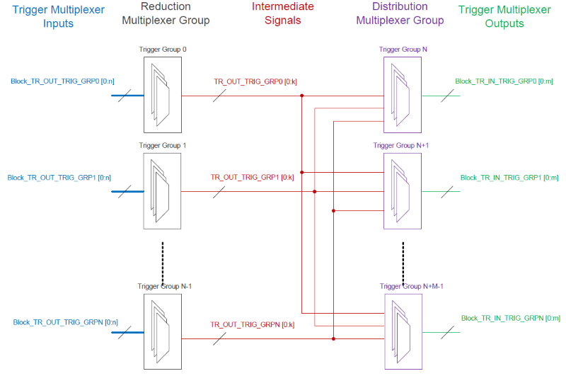
The reduction multiplexer groups have input options that are the trigger outputs coming from the different peripheral blocks and the reduction multiplexer groups route them to intermediate signals. The distribution multiplexer groups have input options from these intermediate signals and route them back to multiple peripheral blocks as their trigger inputs.
For PERI_ver2: The trigger multiplexer groups structure is flat - all the groups are essentially distribution multiplexers (there are no any intermediate trigger signals), so the structure is simpler in comparison with PERI_ver1, however a bit less flexible. Additionally there are another type of trigger interconnections: one-to-one trigger lines. These are not multiplexers, only single trigger wires from/to the dedicated peripherals. Multiple groups of one-to-one trigger lines significantly improve the whole triggering interconnect system flexibility.
The trigger architecture of the PSoC device is explained in the technical reference manual (TRM). Refer to the TRM to better understand the trigger multiplexer routing architecture available.
For PERI_ver1: To route a trigger signal from one peripheral in the PSoC to another, the user must configure a reduction multiplexer and a distribution multiplexer. The Cy_TrigMux_Connect is used to configure a trigger multiplexer connection. The user will need two calls of this API, one for the reduction multiplexer and another for the distribution multiplexer, to achieve the trigger connection from a source peripheral to a destination peripheral.
For PERI_ver2: To route a trigger signal from one peripheral in the PSoC device to another, the user can configure either a trigger multiplexer using Cy_TrigMux_Connect or a one-to-one trigger line using Cy_TrigMux_Select. Only one function call is required to connect one peripheral to another (unlike for PERI_ver1).
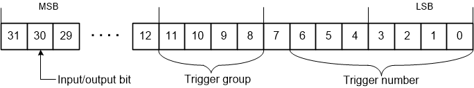
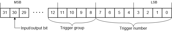
The Cy_TrigMux_Connect() function has two main parameters, inTrig and outTrig that refer to the input and output trigger lines connected using the multiplexer. These parameters are represented in the following format:
For PERI_ver1:
For PERI_ver2:
In addition, the Cy_TrigMux_Connect function also has an invert and trigger type parameter. Refer to the API reference for a detailed description of this parameter. All the constants associated with the different trigger signals in the system (input and output) are defined as constants in the device configuration header file.
For PERI_ver1: The constants for TrigMux in the device configuration header file are divided into four types based on the signal being input/output and being part of a reduction/distribution trigger multiplexer.
The four types of the input/output parameters are: 1) The parameters for the reduction multiplexer's inputs (input signals of TrigMux); 2) The parameters for the reduction multiplexer's outputs (intermediate signals); 3) The parameters for the distribution multiplexer's inputs (intermediate signals); 4) The parameters for the distribution multiplexer's outputs (output signals of TrigMux).
For PERI_ver2: There are two types of TrigMux signal definitions in the device configuration header: 1) The parameters for the trigger interconnection system input signals. 2) The parameters for the trigger interconnection system output signals. Also there are separate groups of trigger multiplexer input/outputs and groups of trigger one-to-one line input/outputs.
Refer to the TRM for a more detailed description of this architecture and different options.
The steps to connect one peripheral block to the other:
For PERI_ver1: Step 1. Find the trigger group number in the Trigger Group Inputs section of the device configuration header file that corresponds to the output of the source peripheral block. For example, TRIG11_IN_TCPWM0_TR_OVERFLOW0 (see Reduction Trigger Mutiplexer Inputs and the diagram at the top of this section) input of the Reduction multiplexers belongs to Trigger Group 11.
Step 2. Find the trigger group number in the Trigger Group Outputs section of the device configuration header file that corresponds to the input of the destination peripheral block. For example, TRIG0_OUT_CPUSS_DW0_TR_IN0 (see Distribution Trigger Mutiplexer Outputs) output of the Distribution multiplexer belongs to Trigger Group 0.
Step 3. Find the same trigger group number in the Trigger Group Inputs section of the device configuration header file that corresponds to the trigger group number found in Step 1. Select the Reduction multiplexer output that can be connected to the trigger group found in Step 2. For example, TRIG0_IN_TR_GROUP11_OUTPUT0 (see Distribution Trigger Mutiplexer Inputs) means that Reduction Multiplexer Output 0 of Trigger Group 11 can be connected to Trigger Group 0.
Step 4. Find the same trigger group number in the Trigger Group Outputs section of the device configuration header file that corresponds to the trigger group number found in Step 2. Select the distribution multiplexer input that can be connected to the trigger group found in Step 1. For example, TRIG11_OUT_TR_GROUP0_INPUT9 (see Reduction Trigger Mutiplexer Outputs) means that the Distribution Multiplexer Input 9 of Trigger Group 0 can be connected to the output of the Reduction multiplexer in Trigger Group 11 found in Step 3.
Step 5. Call Cy_TrigMux_Connect() API twice: the first call - with the constants for the inTrig and outTrig parameters found in Steps 1 and Step 4, the second call - with the constants for the inTrig and outTrig parameters found in Steps 2 and Step 3. For example:
For PERI_ver2: Step 1. Find the trigger group number in the Trigger Group Inputs section of the device configuration header file that corresponds to the output of the source peripheral block. For example, TRIG_IN_MUX_0_TCPWM0_TR_OVERFLOW0 (see Trigger Mutiplexer Inputs) TrigMux input belongs to Trigger Group 0. It is the same TCPWM0 counter 0 overflow output (as in the example for PERI_ver1).
Step 2. Find the same trigger group number in the Trigger Group Outputs section of the device configuration header file that corresponds to the trigger group number found in Step 1. Select the TrigMux output that can be connected to the destination peripheral block. For example, TRIG_OUT_MUX_0_PDMA0_TR_IN0 (see Trigger Mutiplexer Outputs) means that the trigger multiplexer Output 0 of Trigger Group 0 can be connected to the DW0 channel 0 trigger input (the same DMA channel as mentioned in the example for PERI_ver1).
Step 3. Call Cy_TrigMux_Connect() API once:
For more information on the TrigMux peripheral, refer to the technical reference manual (TRM).
| Version | Changes | Reason for Change |
|---|---|---|
| 1.70 | Updated Cy_TrigMux_SwTrigger and Cy_TrigMux_Connect APIs. | Performance enhancement and bug fixes. |
| 1.60.1 | Updated Cy_TrigMux_SwTrigger API. | Coverity error fixes. |
| 1.60 | Updated Cy_TrigMux_SwTrigger API and added CY_TRIGMUX_INTRIG_MASK macro. | Support for CAT1D Devices added. |
| 1.50 | Updated driver to support the CAT1C family of devices. | Added new family of devices. |
| 1.40 | Fixed MISRA violation. | MISRA compliance. |
| 1.30 | Minor bug fixes. | Keep device specific changes under a compile time device flag. |
| Added new device support. | Added new family of device. | |
| 1.20.3 | Minor documentation updates. | Removed MISRA 2004 compliance details and verified MISRA 2012 compliance. |
| 1.20.2 | Minor documentation updates. | Documentation enhancement. |
| 1.20.1 | Documentation is extended/improved. | Enhancement based on usability feedback. |
| 1.20 | Flattened the organization of the driver source code into the single source directory and the single include directory. | Driver library directory-structure simplification. |
Added new API functions: Modified the Cy_TrigMux_SwTrigger API function logic. | New devices support. | |
| Added register access layer. Use register access macros instead of direct register access using dereferenced pointers. | Makes register access device-independent, so that the PDL does not need to be recompiled for each supported part number. | |
| 1.10.1 | Renamed the internal macro in Cy_TrigMux_Connect() function to CY_TRIGMUX_IS_TRIGTYPE_VALID. | |
| 1.10 | The input/output bit in the trigLine parameter of the Cy_TrigMux_SwTrigger() function is changed to 30. The invert parameter type is changed to bool. Added input parameter validation to the API functions. | |
| 1.0 | Initial version |
API Reference | |
| Macros | |
| Functions | |
| Enumerated Types | |
Functions | |
| __STATIC_INLINE cy_en_trigmux_status_t | Cy_TrigMux_SwTrigger (uint32_t trigLine, uint32_t cycles) |
| This function generates a software trigger on an input trigger line. More... | |
| __STATIC_INLINE cy_en_trigmux_status_t Cy_TrigMux_SwTrigger | ( | uint32_t | trigLine, |
| uint32_t | cycles | ||
| ) |
This function generates a software trigger on an input trigger line.
All output triggers connected to this input trigger will be triggered. The function also verifies that there is no activated trigger before generating another activation.
| trigLine | The input of the trigger mux.
|
| cycles | The number of "Clk_Peri" cycles during which the trigger remains activated. For PERI_ver1: The valid range of cycles is 1 ... 254. For PERI_ver2: The only valid value of cycles is 2 (CY_TRIGGER_TWO_CYCLES). Also there are special values (supported with both PERI_ver1 and PERI_ver2):
|