 |
MTB CAT1 Peripheral driver library
|
|
MTB CAT1 Peripheral driver library
|
This driver provides API functions to configure the SAR ADC subsystem within High Power Programmable Analog Sub-System.
HPPASS SAR key features:
The internal structure of the HPPASS SAR ADC is shown below.
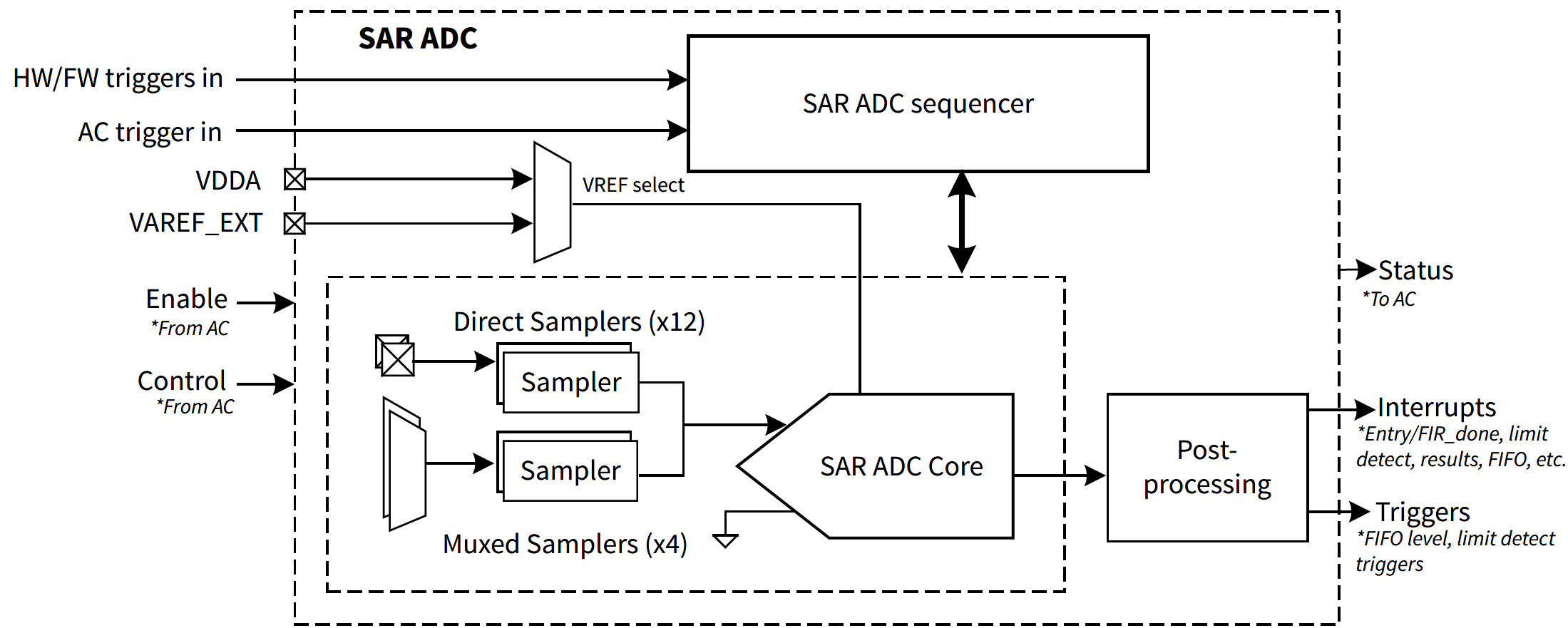
HPPASS SAR consists of SAR Sequencer, samplers, SAR ADC core and post-processing blocks. There are two types of samplers: direct and muxed. First 12 samplers are direct samplers, each connected to its own dedicated analog input, forming first 12 SAR channels. Last 4 samplers are muxed samplers, each can be connected to one of 4 shared analog inputs through the analog multiplexer, forming last 16 SAR channels. Although HPPASS supports 28 SAR channels in total, some channels may not be available on certain devices or be reserved. Refer to the device datasheet and reference manual for HPPASS SAR analog input pins mapping.
The internal structure of the HPPASS SAR sequencer is shown below.
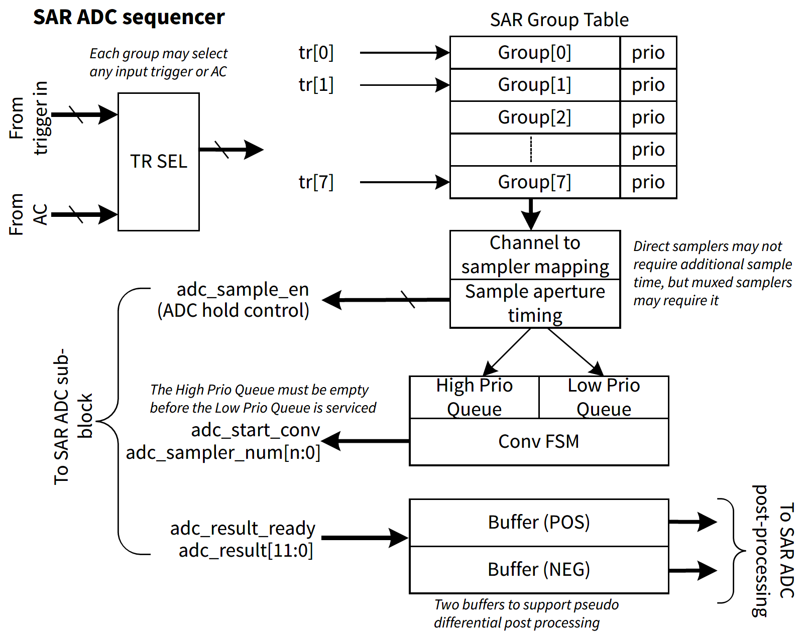
Operation of the SAR sequencer is controlled by the cy_stc_hppass_sar_grp_t configuration structures. HPPASS supports up to 8 SAR sequencer groups, each group can be configured to perform measurements on any combination of direct and muxed samplers with selected input trigger, sample time and priority.
In SAR sequencer group, direct samplers can be enabled by setting corresponding bit in cy_stc_hppass_sar_grp_t::dirSampMsk field, while muxed samplers are enabled by setting cy_stc_hppass_sar_grp_t::muxSampMsk field.
The SAR sequencer group can be triggered by HPPASS Input Trigger or AC (cy_stc_hppass_sar_grp_t::trig). To trigger selected group from the firmware, set cy_stc_hppass_sar_grp_t::trig to one of 8 HPPASS input triggers (cy_en_hppass_sar_trig_t) and configure selected input trigger in firmware mode by setting cy_stc_hppass_sar_grp_t::trig to CY_HPPASS_TR_FW_PULSE or CY_HPPASS_TR_FW_LEVEL. To start the group conversion, call Cy_HPPASS_SetFwTrigger function with the same trigger in the mask parameter.
The SAR sequencer group can perform immediate input sampling or include addition sample time for all enabled samplers. HPPASS SAR supports 3 different sample time settings, which are configured in cy_stc_hppass_sar_t::sampTime and selected for each SAR sequencer group in cy_stc_hppass_sar_grp_t::sampTime field.
SAR sequencer group can be configured to be put in high or low priority conversion queue. High-priority groups are always converted before low-priority groups and are guaranteed to be converted before sampler leakage renders the sample invalid. However, low-priority groups may be in the hold state for too long. Check the Cy_HPPASS_SAR_GetHoldViolationStatus function status to ensure that low-priority groups were converted before they expired.
Additionally, the SAR sequencer group can be configured in Continuous mode, where the group is retriggered automatically after the previous conversion is complete. This mode is configured in cy_stc_hppass_sar_grp_t::continuous field. In Continuous mode, the group can be stopped by calling Cy_HPPASS_SAR_DisableGroupContConvert function.
Configuration snippet for one shot SAR application. Startup SAR state enables SAR. One shot SAR measurement state triggers SAR to perform one measurement.
Functional snippet Application flow:
To configure the SAR Group or Results interrupts in addition to the SAR and AC configuration tables, as shown in the snippet above, declare your own interrupt configuration structure for each interrupt source, for example:
and initialize those configurations in the executable code. That code can be designed as a separate function (see the snippet below):
Also, initialize the NVIC through a separate function as well.
The interrupt service routine for each of the interrupt sources must be implemented in the project. One of those interrupt service routines is shown below:
The configuration and initialization sequence for SAR interrupts is shown in the snippet below:
To generate SAR Limit or Limits interrupts, configure one or more limits and determine the limit for each SAR channel if needed.
That configurations must be also included in the fields of the SAR configuration structure (cy_stc_hppass_sar_t):
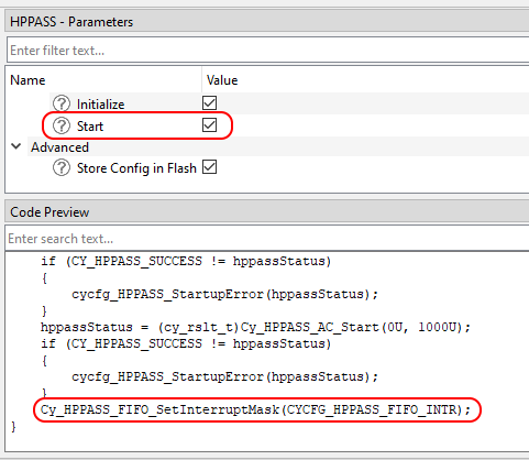
Using FIFO with MTB Device Configurator, since the FIFO has a single interrupt vector and need to be integrated with different solution personalities (like Motor Control) the Device Configurator itself generates the interrupt handler for entire FIFO with possibility to register individual callback for each FIFO buffer. See the generated source cycfg_peripherals.c for details. The runtime FIFO interrupt control can be done by the Cy_HPPASS_FIFO_SetInterruptMask. The Device Configurator also generates the CYCFG_HPPASS_FIFO_INTR definition - the mask of all the used FIFO interrupt flags, which can be used with Cy_HPPASS_FIFO_SetInterruptMask. When the HPPASS configurator 'start' feature is used - the Cy_HPPASS_FIFO_SetInterruptMask(CYCFG_HPPASS_FIFO_INTR) shall be called automatically during the generated init_cycfg_peripherals(); execution.
The Device Configurator generated HPPASS FIFO interrupt priority is 0 (because it is intended to drive the solution fast control loop), however it could be changed manually in the generated cycfg_HPPASS_FIFO_interrupt structure before the generated cycfg_HPPASS_FIFO_ISR_Init() execution (when the HPPASS Startup Initialize feature is disabled).
The finite impulse response (FIR) is a generalized filter structure that allows getting all of the basic response types through varying its coefficients. Although the FIR structure allows implementing Low-pass filter (LPF), High-pass filter (HPF), Band-pass filter (BPF), and Band-stop filter (BSF), the recommended filter implementation in HPPASS CSG module is the LPF. Such a recommendation is based on a hardware HPPASS SAR FIR limitation, which is a maximum number of tap count equal to 16 taps. You can use any available FIR Calculator or FIR Design Tool for coefficient determination.
However, the chosen tool must allow you to:
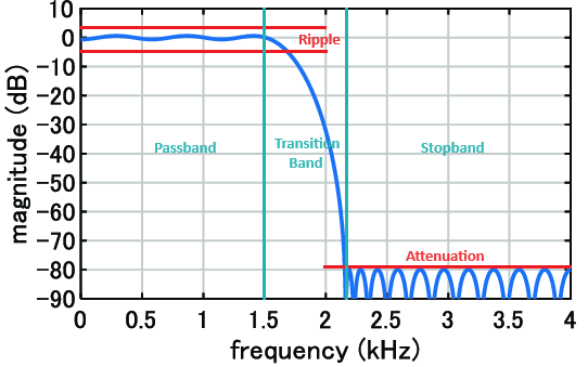
There are various methods for FIR filter design to calculate FIR coefficients. Some tools allow you to choose the design method, but regardless of the exact chosen method, most FIR design tools require determining the desired frequency response parameters.
Generally, in case of the LPF FIR design that will be:
The design method and parameters chosen ultimately determine the values of the filter coefficients.
After configuring the FIR filter and calculating the coefficients, you must check the obtained coefficient values. Due to the hardware HPPASS SAR FIR limitation, all filter coefficients must satisfy the conditions:
If the obtained coefficients didn't comply with these conditions, you must change the FIR filter configurations. The most impact parameters to change the coefficients' values are the Sample Frequency and Transition Band width.
After calculating the coefficients and verifying the conditions, you must convert the floating-point coefficients to a fixed-point representation supported by the hardware.
The HPPASS SAR FIR stores its coefficients in the less significant 16 bits of the 32-bit registers in Q15 fixed-point format.
To convert the floating-point coefficients to a Q15 fixed-point representation, use the equation below:
API Reference | |
| Macros | |
| Functions | |
| Data Structures | |
| Enumerated Types | |