|
CAT2 Peripheral Driver Library
|
|
CAT2 Peripheral Driver Library
|
The iso UART is a point-to-point differential current edge-triggered UART interface for communication with the other battery management system (BMS) ICs. More...
Modules | |
| Macros | |
| Functions | |
| Data Structures | |
| Enumerated Types | |
The iso UART is a point-to-point differential current edge-triggered UART interface for communication with the other battery management system (BMS) ICs.
The functions and other declarations used in this driver are in cy_isouart.h. You can include cy_pdl.h to get access to all functions and declarations in the PDL.
The iso UART can be configured to operate in different modes: Master (Host) or Slave (Node). This protocol consists of a single master device and multiple slave devices. The master device can address the slave devices using node-id and block id. It provides galvanic isolation with UART-style frames (start bit, stop bit, 8 data bits, zero parity bits), and has high robustness against external noise.
The iso UART communicates via two physical links: high side interface (IFH) and low side interface (IFL). Both high and low side interfaces can drive the differential lines (TX) and both have a differential receiver circuit (RX). This offers the necessary isolation to guarantee error-free communication between different modules in the battery system. The interface allowed to drive the bus lines is determined by the bus timing protocol.
The protocol supports up to 30 devices in a single chain using device IDs. This can be extended to more than 30 devices using Block ID. Block ID can also be used to group devices and limit the number of devices responding to broadcast messages. There are two possible topologies: Master-on-Bottom (MOB) and Master-on-Top (MOT). These topologies can also be optionally wired as complete loops (Ring).
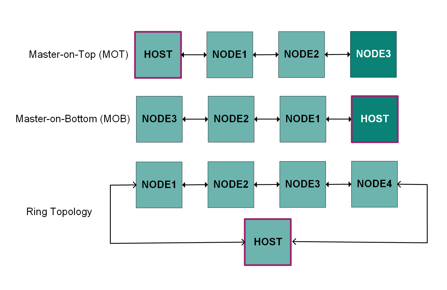
Master-on-Top (MOT):
Master-on-Bottom (MOB):
Ring Topologies (MOT-Ring, MOB-Ring):
Both high side (IFH) and low side (IFL) interfaces can act as transmitters and receivers. Nodes automatically detect the wake signal source and configure their internal multiplexer to receive commands from the appropriate interface while simultaneously forwarding frames through the chain via the opposite interface. When transmitting a response, the slave transmits on both High and Low interfaces simultaneously.
The iso UART protocol supports six command types for Host-Node communication, with two main categories: write and read requests that differ primarily in Address/ID field content. All frames are hardware-interpreted and use 8-bit data with full CRC protection (no parity). The protocol tolerates frequency mismatch between Host and Node transmissions and supports broadcast operations.
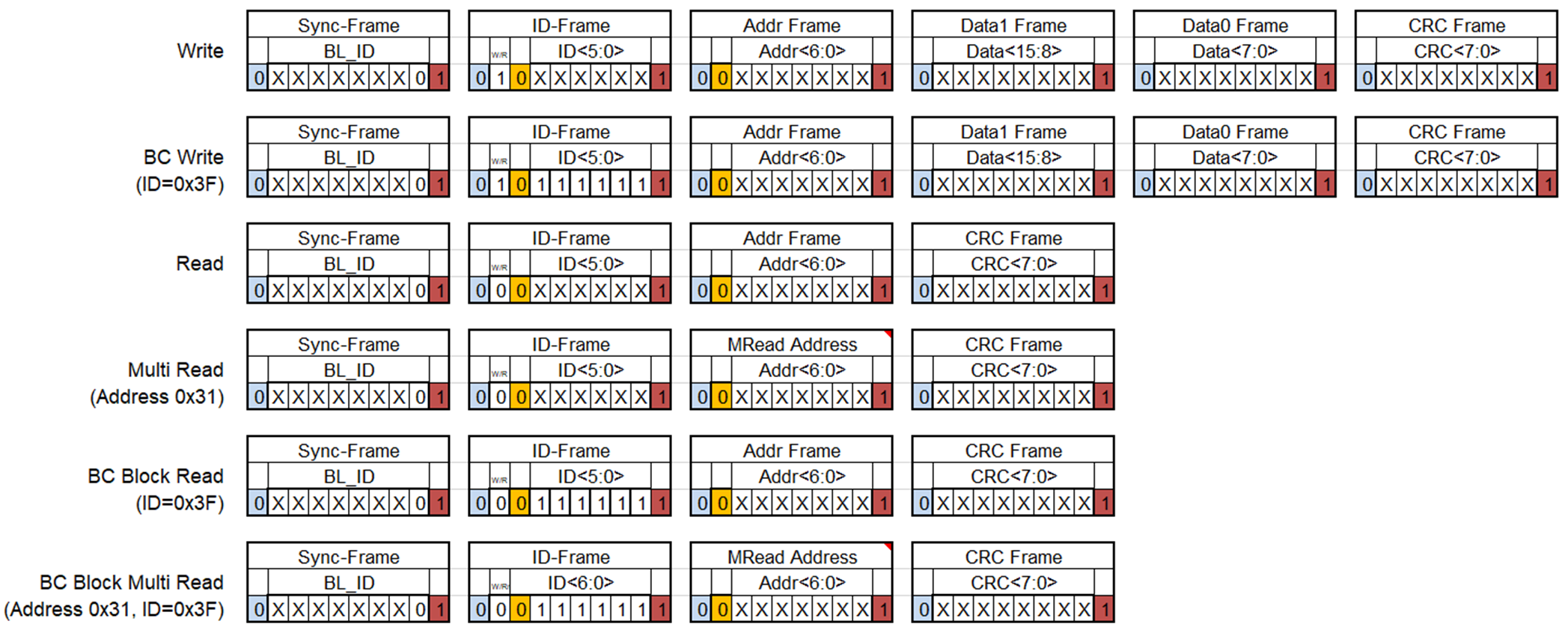
Write Commands:
The Host can write data to Node registers or SRAM locations using several write command types:
When executing write commands, Nodes return Write Reply messages containing operation status information (CRC, status flags, error bits) stored in HIGH_INTERFACE_READ or LOW_INTERFACE_READ registers. Standard Write commands receive a response from the addressed Node, while Broadcast Write commands receive a response from the final Node in the chain. It is essential for broadcast write mode that the final Node in the chain must be properly marked with FN=1 (Final Node flag) during the enumeration process. If no Node has FN=1 set, Broadcast Write commands will not receive any Write Reply frame, resulting in a FRAME ERROR. This configuration is essential for proper broadcast communication functionality.
Read Commands:
The Host can read data from Node registers or SRAM locations using several read command types:
Two non-data notifications commands:
The iso UART block contains the 128 x 32-bit SRAM, which serves as the primary memory for data storage and exchange. It is the only interface between the iso UART peripheral and the rest of the chip via CPU or DMA. The SRAM defaults to an unexpected state and must be initialized and divided before iso UART block is enabled.
SRAM Word Structure (32 bits):
The 128-word SRAM can be divided into two parts Low and High, with each part being dedicated to store data received from corresponding interface in certain receive modes.
The iso UART provides three distinct receiver modes that determine how incoming frame data is processed and stored in SRAM:
In Unpacked and Raw modes, data is written to both SRAM and interface registers, with optional ECC calculation for enhanced data integrity protection. Register mode writes data only to interface registers without using SRAM.
The ModusToolbox Device Configurator provides a graphical user interface to configure the iso UART peripheral. This tool automatically generates initialization code and configuration structures based on your settings.
To use the Device Configurator:
After Device Configurator is set up, the initialization structures, clocks, peripheral clock dividers, GPIOs, and other peripheral configuration code are auto-generated and placed in ../bsps/TARGET_APP_.../config directory files.
Place the call of the cybsp_init() function before using any iso UART API functions to ensure initialization of all external resources required for the iso UART operation.
To set up the iso UART driver in the Host mode, provide the configuration parameters in the cy_stc_isouart_host_config_t structure. Host configuration requires careful consideration of topology, receiver mode, CRC policy, block ID usage, and multi-read settings to match those configured on the nodes in the physical chain setup. To initialize the driver, call the Cy_ISOUART_HostInit function providing a pointer to the populated cy_stc_isouart_host_config_t structure.
To set up the iso UART driver in the Node mode, provide the configuration parameters in the cy_stc_isouart_node_config_t structure. Node configuration must be compatible with the host configuration, especially regarding CRC policy, Block ID usage, and multi-read settings. To initialize the driver, call Cy_ISOUART_NodeInit function providing a pointer to the populated cy_stc_isouart_node_config_t structure.
The iso UART block requires proper configuration of high frequency clock (HFCLK) and peripheral dividers to operate at 24 MHz. This clock is configured using the SysClk (System Clock) driver API.
The iso UART can use interrupts to handle communication events. Configuration flow includes setting up the interrupt service routine (ISR) and enabling the appropriate interrupt sources.
The iso UART must be enabled to operate. This includes enabling the peripheral and global interrupts.
The multi-read feature allows reading multiple registers from a Node using pre-configured address ranges. To use this feature, the multi-read configuration must be set via broadcast write before use.
This section demonstrates a typical iso UART Host and Node implementation using the following configuration:
This section demonstrates how to configure a Host to communicate with Nodes in the chain. The Host can be configured using either auto-generated code from Device Configurator Setup or manual configuration as described in Host Configuration, Clock Configuration, Interrupt Configuration, and Enable Iso UART sections.
Enumeration Process
Before starting communication, the Host must enumerate each Node in the chain to assign unique IDs. This process is required at a startup and after a wake-up from Sleep mode, as Node-IDs are reset to 0. The Host sequentially assigns IDs by sending write commands to Device ID 0, starting from 1. Every enumerated Node starts forwarding messages which allow access to the next Node with ID 0. This continues until all Nodes receive consecutive IDs, with the final Node marked appropriately:
Write Operations
The Host writes data to Node registers or SRAM using Cy_ISOUART_HostSendWriteCommand. This function supports both individual Node writes and broadcast writes to all Nodes simultaneously (for broadcast mode, set the nodeId parameter to 63).
After every write operation, Nodes return Write Reply frames containing operation status information such as CRC validation, error flags, and operation status. These replies are stored in HIGH_INTERFACE_READ or LOW_INTERFACE_READ registers. If any error bits are set in the reply (status, access, or address errors), the Host triggers the corresponding interrupts: CY_ISOUART_INTR_MASTER_SLAVE_STATUS_ERROR, CY_ISOUART_INTR_MASTER_SLAVE_ACCESS_ERROR, or CY_ISOUART_INTR_MASTER_SLAVE_ADDRESS_ERROR. Additionally, if the CRC doesn't match the expected value, the Host triggers CY_ISOUART_INTR_MASTER_CRC_ERROR interrupt.
To process the write reply, there are two approaches for CRC validation. You can enable the CY_ISOUART_INTR_MASTER_CRC_ERROR interrupt or, alternatively, you can use manual validation by reading the reply data with Cy_ISOUART_HostReadLowInterface or Cy_ISOUART_HostReadHighInterface (depending on your topology configuration) and then passing this value to Cy_ISOUART_HostVerifyCRC to validate the CRC value.
Read Operations
The Host can read data from Node registers or SRAM locations using Cy_ISOUART_HostSendReadCommand. Received data is stored in SRAM and can be retrieved using appropriate API functions based on the configured receiver mode: Cy_ISOUART_HostReadSramUnpack for Unpacked mode, Cy_ISOUART_HostReadSramRaw for Raw mode (returns complete packet with addr, nodeID, data, CRC fields, or use Cy_ISOUART_ReadSramRow16 / Cy_ISOUART_ReadSramRow32 for direct data field access), or Cy_ISOUART_HostReadLowInterface / Cy_ISOUART_HostReadHighInterface for Register mode:
This section demonstrates how to configure a Node to receive and process commands from the Host. The Node can be configured using either auto-generated code from Device Configurator Setup or manual configuration as described in Node Configuration, Clock Configuration, Interrupt Configuration, and Enable Iso UART sections.
Trigger Interrupts Structures and Attributes Configuration
To properly handle Host commands, the Node must be configured to monitor-specific SRAM addresses and trigger actions based on received data. This requires configuring interrupt trigger structures and linking them to specific SRAM row attributes:
Implementing the Interrupt Handler
The Node's interrupt handler processes incoming write commands from the Host and executes appropriate responses. Note that proper interrupt configuration (as described in Interrupt Configuration) must be completed before this handler can function correctly:
Maintaining Node Activity
The Node contains a 7-bit watchdog counter that counts downward from its maximum value and must be serviced regularly to prevent the device from entering Sleep mode. The watchdog operates with a 16ms resolution on a 24MHz clock, and so provide a maximum timeout of 2.03 seconds. This watchdog timer must be refreshed periodically before it reaches zero using Cy_ISOUART_NodeSetWdtCount on the Node or using Cy_ISOUART_HostSendWriteCommand on the Host side.
Refreshing watchdog counter from Host:
Refreshing watchdog counter on the Node:
The iso UART provides mechanisms to protect SRAM addresses on Nodes using Cy_ISOUART_NodeConfigSramRowAttr. Two protection modes are available:
Invalid Address Protection
When a Node marks a SRAM address as invalid using Cy_ISOUART_NodeConfigSramRowAttr, any Host read or write attempt to that address will be rejected. For write commands, the Node responds with the address error bit set in the reply frame, triggering the CY_ISOUART_INTR_MASTER_SLAVE_ADDRESS_ERROR interrupt on the Host side.
Node-side configuration:
Host-side error handling:
Read-Only Protection
When a Node marks a SRAM address as read-only using Cy_ISOUART_NodeConfigSramRowAttr, write attempts from the Host will be rejected while read operations remain allowed. The Node responds with the access error bit set in the reply frame, triggering the CY_ISOUART_INTR_MASTER_SLAVE_ACCESS_ERROR interrupt on the Host side.
Node-side configuration:
Host-side error handling:
See the Iso UART chapter of the device technical reference manual (TRM).
| Version | Changes | Reason for Change |
|---|---|---|
| 1.0 | The initial version. |