|
PSOC E8XXGP Device Support Library
|
|
PSOC E8XXGP Device Support Library
|
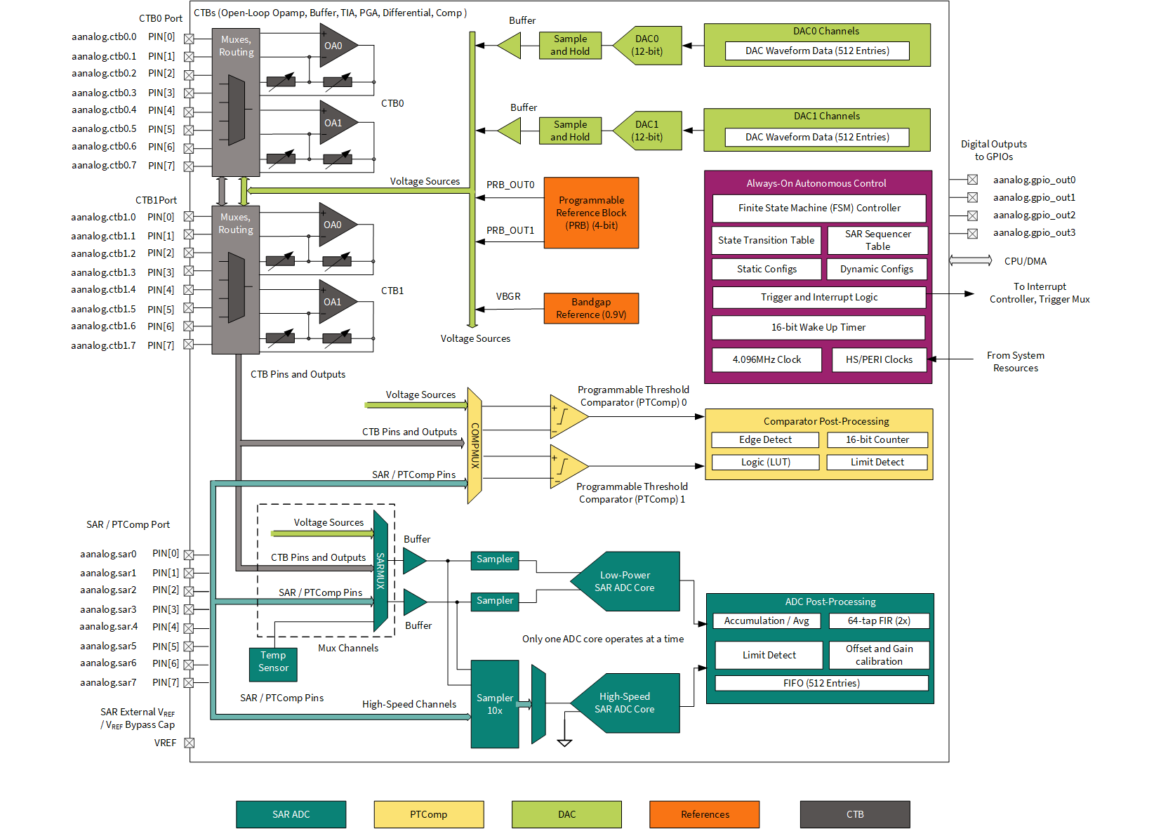
This driver provides API functions to configure the Autonomous Analog.
The Autonomous Analog can sense a voltage or current, convert it to digital code, post process conversion data, and thus make the first-level decisions as close to the sensor as possible.
It is a low power reconfigurable mixed signal sense, condition, and respond system, which can be fully functional and autonomous in all power modes except Hibernate (see Power Modes chapter for the device).
The Autonomous Analog is entirely controlled and determined by a Finite-State Machine sequencer, (see AC (Autonomous Controller) for more details) which works of a State Transition Table (see cy_stc_autanalog_stt_t for more details), to transition appropriately through various pre-defined states, based on the Timer and/or Events.
The following diagram shows the subsystems of the Autonomous Analog. See the device datasheet for the exact location of pins.
The Autonomous Analog can use the following externally supplied clocks:
SRSS low frequency clock CLK_LF 32kHz used for AC wake-up Timer,
refer to the AC wake-up Timer configuration structure cy_stc_autanalog_timer_t
The Autonomous Analog can use a locally generated Vref (refer to the PRB configuration structure cy_stc_autanalog_prb_cfg_t) or
a Vref supplied externally via the pin (refer to Reference Voltage chapter for SAR ADC)
The steps to generate initialization code using the ModusToolbox Device Configurator:
For more information on the Autonomous Analog, refer to the device Architecture Technical Reference Manual (TRM).
API Reference | |
| AC (Autonomous Controller) | |
| This driver provides API functions to configure the Autonomous Controller (AC) subsystem within the Autonomous Analog. | |
| CTB (Continuous Time Block) | |
| This driver provides API functions to configure the CTB subsystem of the Autonomous Analog. | |
| PTComp (Programmable Threshold Comparator) | |
| This driver provides API functions to configure the PTComp subsystem of the Autonomous Analog. | |
| CT DAC (Continuous Time Digital to Analog Converter) | |
| This driver provides API functions to configure the CT DAC subsystem of the Autonomous Analog. | |
| SAR ADC (Successive-Approximation Register Analog to Digital Converter) | |
| This driver provides the API functions to configure the successive approximation register analog-to-digital converter (SAR ADC) subsystem of the Autonomous Analog. | |
| FIFO (The buffer block to store collected data) | |
| The FIFO subsystem is used to store the ADC data or the FIR filter results. | |
| General section of the API | |