|
PSOC E8XXGP Device Support Library
|
|
PSOC E8XXGP Device Support Library
|
Use the System Power Management (SysPm) driver to change power modes and reduce system power consumption in power sensitive designs.
The functions and other declarations used in this driver are in cy_syspm.h. You can include cy_pdl.h to get access to all functions and declarations in the PDL.
For multi-CPU devices, this library allows you to individually enter low power modes for each CPU.
This document contains the following topics:
This device adopts the ARM Power Control Architecture. It supports the following power modes:
To set system LP mode you need to set LP voltage for the active core regulator:
After switching into system LP mode, the operating frequency and current consumption may now be increased up to LP Limitations. The wait states for flash may be changed to increase device performance by calling SysLib function Cy_SysLib_SetWaitStates(true, hfClkFreqMz), where hfClkFreqMz is the frequency of HfClk0 in MHz.
When the system is in LP mode, the core regulator voltage is set to 1.1 V (nominal) and the following limitations must be met:
Before switching into system ULP mode, ensure that the device meets ULP Limitations. Decrease the clock frequencies, and slow or disable peripherals. Also ensure that appropriate wait state values are set for the flash. Flash wait states can be set by calling SysLib function Cy_SysLib_SetWaitStates(true, hfClkFreqMz), where hfClkFreqMz is the frequency of HfClk0 in MHz.
After the ULP Limitations are met and appropriate wait states are set, you must set ULP voltage for the active core regulator:
When the system is in ULP mode the core regulator voltage is set to 0.9 V (nominal) and the following limitations must be meet:
Call Cy_SysPm_SystemLpActiveEnter() to enter LPACTIVE/LPSLEEP mode and Cy_SysPm_SystemLpActiveExit() to exit.
For multi-CPU devices, the Cy_SysPm_CpuEnterSleep() switches only the CPU that calls the function into the CPU Sleep power mode.
All pending interrupts must be cleared before the CPU is put into a Sleep mode, even if they are masked.
The CPU event register can be set in the past, for example, as a result of internal system calls. So an old event can cause the CPU to not enter Sleep mode upon WFE(). Therefore usually the WFE() is used in an idle loop or polling loop as it might or might not cause entering of CPU Sleep mode. If the idle loop or polling loop is not used, then it is recommended to use WFI() instruction.
For multi-CPU devices, the Cy_SysPm_CpuEnterDeepSleep() function switches only the CPU that calls the function into the CPU Deep Sleep power mode. To set the whole system into Deep Sleep power mode, ensure that all CPUs call the Cy_SysPm_CpuEnterDeepSleep() function.
For multi-CPU devices, the Cy_SysPm_CpuEnterDeepSleep() function switches only the CPU that calls the function into the CPU DEEPSLEEP-RAM power mode. To set the whole system into Deep Sleep power mode, ensure that all CPUs call the Cy_SysPm_CpuEnterDeepSleep() function.
For multi-CPU devices, the Cy_SysPm_CpuEnterDeepSleep() function switches only the CPU that calls the function into the CPU DEEPSLEEP-OFF power mode. To set the whole system into Deep Sleep power mode, ensure that all CPUs call the Cy_SysPm_CpuEnterDeepSleep() function.
There are situations when the system does not switch into the Deep Sleep power mode immediately after the last CPU calls Cy_SysPm_CpuEnterDeepSleep(). The system will switch into Deep Sleep mode automatically a short time later, after the low power circuits are ready to switch into Deep Sleep. Refer to the Cy_SysPm_CpuEnterDeepSleep() description for more detail.
All pending interrupts must be cleared before the system is put into a Deep Sleep mode, even if they are masked.
The CPU event register can be set in the past, for example, as a result of internal system calls. So an old event can cause the CPU to not enter Deep Sleep mode upon WFE(). Therefore usually the WFE() is used in an idle loop or polling loop as it might or might not cause entering of CPU Deep Sleep mode. If the idle loop or polling loop is not used, then it is recommended to use WFI() instruction.
For single-CPU devices, SysPm functions that return the status of the unsupported CPU always return CY_SYSPM_STATUS_<CPU>_DEEPSLEEP.
For Arm-based devices, an interrupt is required for the CPU to wake up. For multi-CPU devices, one CPU can wake up the other CPU by sending the event instruction. Use the Cy_SysPm_CpuSendWakeupEvent() function.
If you call Cy_SysPm_SystemEnterHibernate() from either CPU, the system will be switched into the Hibernate power mode directly, because there is no handshake between CPUs.
The system can wake up from Hibernate mode by configuring the following wakeup sources:
Wakeup is supported from device specific pin(s) with programmable polarity. Additionally, unregulated peripherals can wake the system under some conditions. For example, a low power comparator can wake the system by comparing two external voltages, but does not support comparison to an internally-generated voltage. The backup power domain remains functional, and if present it can schedule an alarm to wake the system from Hibernate using the RTC. Alternatively, the Watchdog Timer (WDT) can be configured to wake-up the system by WDT interrupt. Refer to Cy_SysPm_SetHibernateWakeupSource() for more detail.
The system operates in three defined active modes, each tailored for specific performance and power requirements:
Transitioning between these operational modes requires meticulous adherence to defined sequences to prevent timing-related issues. The application is responsible for managing system frequency during these transitions, ensuring it stays within the valid range for both current and target modes. The driver assumes all frequency requirements are met before mode transition APIs are called.
The driver provides dedicated APIs for transitions:
The following sections outline the required conditions and sequence of operations for each supported transition.
To transition the system from Ultra Low Power (ULP) to Low Power (LP) mode, follow these steps in the secure processing environment:
To transition the system from Low Power (LP) to High Power (HP) mode, follow these steps in the secure processing environment:
To transition the system from High Power (HP) to Low Power (LP) mode, follow these steps in the secure processing environment:
To transition the system from Low Power (LP) to Ultra Low Power (ULP) mode, follow these steps in the secure processing environment:
(Levels of Abstraction)
The driver supports two operational abstraction levels for system transitions:
When the system is performing a power transition all the clocks used to access the SRAM must be adapted to the new power mode. The SRAM clock frequency must be reduced before the transition and can be increased after the transition is completed.
In addition to system ULP and LP modes, the five different resource power settings can be configured to reduce current consumption:
These five sub features can modify both system LP or ULP modes as they are independent from LP/ULP settings. When all five sub features are set to their low power modes, the system operates in regulator minimum current mode. In regulator minimum current mode, the system current consumption is limited to a device-specific value. Refer to the device datasheet for the exact current consumption value in regulator minimum current mode.
When all five sub features are set to their normal mode, the system operates in regulator normal current mode. When regulator normal current mode is set, the system may operate at device maximum current.
Before setting the regulator minimum current mode ensure that current limits are be met. After current limits are met, call the Cy_SysPm_SystemSetMinRegulatorCurrent() function.
To set regulator normal current mode, call the Cy_SysPm_SystemSetNormalRegulatorCurrent() function. After the function call, the current limits can be increased to a maximum current, depending on what system power mode is set: LP or ULP.
The SysPm driver handles low power callbacks declared in the application.
If there are no callbacks registered, the device executes the power mode transition. However, frequently your application firmware must make modifications for low power mode. For example, you may need to disable a peripheral, or ensure that a message is not being transmitted or received.
To enable this, the SysPm driver implements a callback mechanism. When a lower power mode transition is about to take place (either entering or exiting System Power Modes), the registered callbacks for that transition are called.
The SysPm driver organizes all the callbacks into a linked list. While entering a low power mode, SysPm goes through that linked list from first to last, executing the callbacks one after another. While exiting low power mode, SysPm goes through that linked list again, but in the opposite direction from last to first. This ordering supports prioritization of callbacks relative to the transition event.
For example, the picture below shows three callback structures organized into a linked list: myDeepSleep1, myDeepSleep2, myDeepSleep3 (represented with the cy_stc_syspm_callback_t configuration structure). Each structure contains, among other fields, the address of the callback function. The code snippets below set this up so that myDeepSleep1 is called first when entering the low power mode. This also means that myDeepSleep1 will be the last one to execute when exiting the low power mode.
The callback structures after registration:
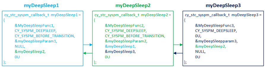
Your application must register each callback, so that SysPm can execute it. Upon registration, the linked list is built by the SysPm driver. Notice the &myDeepSleep1 address in the myDeepSleep1 cy_stc_syspm_callback_t structure. This is filled in by the SysPm driver, when you register myDeepSleep1. The cy_stc_syspm_callback_t.order element defines the order of their execution by the SysPm driver. Call Cy_SysPm_RegisterCallback() to register each callback function.
A callback function is typically associated with a particular driver that handles the peripheral. So the callback mechanism enables a peripheral to prepare for a low power mode (for instance, shutting down the analog part); or to perform tasks while exiting a low power mode (like enabling the analog part again).
With the callback mechanism you can prevent switching into a low power mode if a peripheral is not ready. For example, driver X is in the process of receiving a message. In the callback function implementation simply return CY_SYSPM_FAIL in a response to CY_SYSPM_CHECK_READY.
If success is returned while executing a callback, the SysPm driver calls the next callback and so on to the end of the list. If at some point a callback returns CY_SYSPM_FAIL in response to the CY_SYSPM_CHECK_READY step, all the callbacks that have already executed are executed in reverse order, with the CY_SYSPM_CHECK_FAIL mode parameter. This allows each callback to know that entering the low power mode has failed. The callback can then undo whatever it did to prepare for low power mode, if required. For example, if the driver X callback shut down the analog part, it can re-enable the analog part.
Let's switch to an example explaining the implementation, setup, and registration of three callbacks (myDeepSleep1, myDeepSleep2, myDeepSleep2) in the application. The Callback Configuration Considerations are provided after the SysPm Callbacks Example.
The following code snippets demonstrate how use the SysPm callbacks mechanism. We will build the prototype for an application that registers three callback functions:
We set things up so that the myDeepSleep1 and myDeepSleep2 callbacks do nothing while entering the low power mode (skip on CY_SYSPM_SKIP_BEFORE_TRANSITION - see Callback Function Implementation in Callback Configuration Considerations). Skipping the actions while entering low power might be useful if you need to save time while switching low power modes. This is because the callback function with a skipped mode is not even called avoiding the call and return overhead.
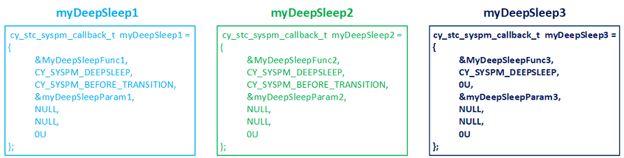
Let's first declare the callback functions. Each gets the pointer to the cy_stc_syspm_callback_params_t structure as the argument.
Now we setup the cy_stc_syspm_callback_params_t structures that we will pass to the callback functions. Note that for the myDeepSleep2 and myDeepSleep3 callbacks we also pass pointers to the peripherals related to that callback (see PDL Design section to learn about base hardware addresses). The configuration considerations related to this structure are described in Callback Function Parameters in Callback Configuration Considerations.
Now we setup the actual callback configuration structures. Each of these contains, among the other fields, the address of the cy_stc_syspm_callback_params_t we just set up. We will use the callback configuration structures later in the code to register the callbacks in the SysPm driver. Again, we set things up so that the myDeepSleep1 and myDeepSleep2 callbacks do nothing while entering the low power mode (skip on CY_SYSPM_SKIP_BEFORE_TRANSITION) - see Callback Function Implementation in Callback Configuration Considerations.
Note that in each case the last two fields are NULL. These are fields used by the SysPm driver to set up the linked list of callback functions.
The callback structures are now defined and allocated in the user's memory space:
Now we implement the callback functions. See Callback Function Implementation in Callback Configuration Considerations for the instructions on how the callback functions should be implemented.
Finally, we register the callbacks so that the SysPm driver knows about them. The order in which the callbacks will be called depends upon the order in which the callbacks are registered. If there are no callbacks registered, the device just executes the power mode transition.
Callbacks that reconfigure global resources, such as clock frequencies, should be registered last. They then modify global resources as the final step before entering the low power mode, and restore those resources first, as the system returns from low power mode.
We are done configuring three callbacks. Now the SysPm driver will execute the callbacks appropriately whenever there is a call to a power mode transition function: Cy_SysPm_CpuEnterSleep(), Cy_SysPm_CpuEnterDeepSleep(), Cy_SysPm_SystemEnterUlp(), Cy_SysPm_SystemEnterLp(), and Cy_SysPm_SystemEnterHibernate().
Refer to Callback Unregistering in Callback Configuration Considerations to learn what to do if you need to remove the callback from the linked list. You might want to unregister the callback for debug purposes.
Refer to Callbacks Execution Flow in Callback Configuration Considerations to learn about how the SysPm processes the callbacks.
The callbackParams parameter of the callback function is a cy_stc_syspm_callback_params_t structure. The second parameter (mode) is for internal use. In the example code we used a dummy value CY_SYSPM_CHECK_READY to eliminate compilation errors associated with the enumeration. The driver sets the mode field to the correct value when calling the callback functions (the mode is referred to as step in the Callback Function Implementation). The callback function reads the value and executes code based on the mode set by the SysPm driver. The base and context fields are optional and can be NULL. Some drivers require a base hardware address and context to store information about the mode transition. If your callback routine requires access to the driver registers or context, provide those values (see PDL Design section to learn about Base Hardware Address). Be aware of MISRA warnings if these parameters are NULL.
For each callback, provide a cy_stc_syspm_callback_t structure. Some fields in this structure are maintained by the driver. Use NULL for cy_stc_syspm_callback_t.prevItm and cy_stc_syspm_callback_t.nextItm. Driver uses these fields to build a linked list of callback functions. The value of cy_stc_syspm_callback_t.order element is used to define the order how the callbacks are put into linked list, and sequentially, how the callbacks are executed. See Callback Registering section.
Every callback function should handle four possible steps (referred to as "mode") defined in cy_en_syspm_callback_mode_t :
A callback function can skip steps (see Defines to skip the callbacks modes). In our example myDeepSleep1 and myDeepSleep2 callbacks do nothing while entering the low power mode (skip on CY_SYSPM_BEFORE_TRANSITION). If there is anything preventing low power mode entry - return CY_SYSPM_FAIL in response to CY_SYSPM_CHECK_READY in your callback implementation. Note that the callback should return CY_SYSPM_FAIL only in response to CY_SYSPM_CHECK_READY. The callback function should always return CY_SYSPM_PASS for other modes: CY_SYSPM_CHECK_FAIL, CY_SYSPM_BEFORE_TRANSITION, and CY_SYSPM_AFTER_TRANSITION (see Callbacks Execution Flow).
This section explains what happens during a power transition, when callbacks are implemented and set up correctly. The following discussion assumes:
User calls one of the power mode transition functions: Cy_SysPm_CpuEnterSleep(), Cy_SysPm_CpuEnterDeepSleep(), Cy_SysPm_SystemEnterUlp(), Cy_SysPm_SystemEnterLp(), or Cy_SysPm_SystemEnterHibernate(). It calls each callback with the mode set to CY_SYSPM_CHECK_READY. This triggers execution of the code for that mode inside of each user callback.
The intent of CY_SYSPM_CHECK_READY is to only signal if the resources is ready to transition. Ideally, no transition changes should be made at this time. In some cases a small change may be required. For example a communication resource callback may set a flag telling firmware not to start any new transition.
If that process is successful for all callbacks, then Cy_SysPm_ExecuteCallback() calls each callback with the mode set to CY_SYSPM_BEFORE_TRANSITION. This triggers execution of the code for that mode inside each user callback. We then enter the low power mode after all callback are executed.
When exiting the low power mode, the SysPm driver executes Cy_SysPm_ExecuteCallback() again. This time it calls each callback in reverse order, with the mode set to CY_SYSPM_AFTER_TRANSITION. This triggers execution of the code for that mode inside each user callback. The final execution of callbacks depends on the low power mode in which callbacks were called:
A callback can return CY_SYSPM_FAIL only while executing the CY_SYSPM_CHECK_READY mode. If that happens, then the remaining callbacks are not executed. Any callbacks that have already executed are called again, in reverse order, with CY_SYSPM_CHECK_FAIL. This allows the system to return to the previous state. If a callback returns a fail then any of the functions (Cy_SysPm_CpuEnterSleep(), Cy_SysPm_CpuEnterDeepSleep(), Cy_SysPm_SystemEnterUlp(), Cy_SysPm_SystemEnterLp(), or Cy_SysPm_SystemEnterHibernate()) that attempt to switch the device into a low power mode will also return CY_SYSPM_FAIL.
Callbacks that reconfigure global resources, such as clock frequencies, should be registered last. They then modify global resources as the final step before entering the low power mode, and restore those resources first, as the system returns from low power mode.
While registration the callback is put into the linked list. The place where the callback structure is put into the linked list is based on cy_stc_syspm_callback_t.order. The callback with the lowest cy_stc_syspm_callback_t.order value will be placed at the beginning of linked list. The callback with the highest cy_stc_syspm_callback_t.order value will be placed at the end of the linked list. If there is already a callback structure in the linked list with the same cy_stc_syspm_callback_t.order value as you attend to register, then your callback will be placed right after such a callback.
Such a registration order defines how the callbacks are executed:
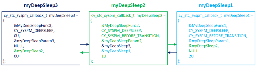
Callbacks with equal cy_stc_syspm_callback_t.order values are registered in the same order as they are registered:
Callbacks with a different cy_stc_syspm_callback_t.order value will be stored based on the cy_stc_syspm_callback_t.order value, with no matter when they when registered:
This can be useful to ensure that system resources (clock dividers, etc) are changed right before entering low power mode and immediately after exiting from low power.
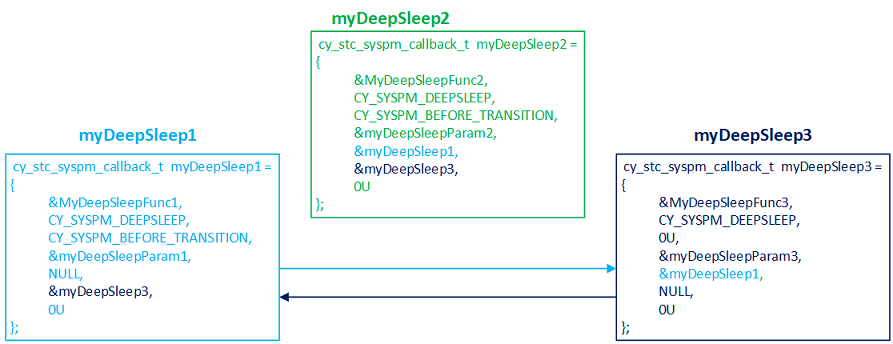
Unregistering the callback might be useful when you need to dynamically manage the callbacks.
The callback structures after myDeepSleep2 callback is unregistered:
Some SYSPM APIs are marked as Secure Aware. This means that if the resource in SYSPM is marked as a secure region in the Peripheral Protection Controller (PPC) and these APIs are called from a non-secure CPU state, the PDL will submit a request to the Secure Request Framework (SRF) middleware to transition to a secure CPU state to perform the operation. From the application's perspective, the API will behave the same whether it is called from a secure or non-secure CPU state albeit slower.
This functionality is automatically enabled on devices with ARM TrustZone processors. To disable, set the DEFINE+=CY_PDL_ENABLE_SECURE_AWARE_SYSPM=0 in the application Makefile.
For more information on Secure Aware PDL behavior, see Secure Aware PDL.
| Term | Definition |
|---|---|
| LDO | Low dropout linear regulator. The functions that manage this block are grouped as LDO under Core Voltage Regulation |
| SIMO Buck | Single inductor multiple Output Buck regulator, referred as "Buck regulator" throughout the documentation. The functions that manage this block are grouped as Buck under Core Voltage Regulation |
| SISO Buck | Single inductor single output Buck regulator, referred as "Buck regulator" throughout the documentation. The functions that manage this block are grouped as Buck under Core Voltage Regulation |
| PMIC | Power management integrated circuit. The functions that manage this block are grouped as group_syspm_functions_pmic |
| LP | System low power mode. See the Switching the System into Low Power section for details. |
| ULP | System ultra low power mode. See the Switching the System into Ultra Low Power section for details. |
For more information on the SysPm driver, refer to the technical reference manual (TRM).
API Reference | |
| PDCM (Power Dependency Control Matrix) | |
| PDCM driver provides APIs for controlling the Power Dependency Control Matrix across Power Domains. | |
| PPU (Power Policy Unit) | |
| Power Domain PPU driver is a platform dependent driver on top of ARM PPU Driver. | |
| Macros | |
| Functions | |
| Data Structures | |
| Enumerated Types | |