CAT2 Peripheral Driver Library

Driver API for I2C Bus Peripheral. More...

Modules

 Macros
 
 Functions
 
 Data Structures
 
 Enumerated Types
 

Detailed Description

Driver API for I2C Bus Peripheral.

I2C - The Inter-Integrated Circuit (I2C) bus is an industry-standard.

The functions and other declarations used in this part of the driver are in cy_scb_i2c.h. You can also include cy_pdl.h to get access to all functions and declarations in the PDL.

The I2C peripheral driver provides an API to implement I2C slave, master, or master-slave devices based on the SCB hardware block. I2C devices based on SCB hardware are compatible with I2C Standard-mode, Fast-mode, and Fast-mode Plus specifications as defined in the I2C-bus specification.

Features:

Configuration Considerations

The I2C driver configuration can be divided to number of sequential steps listed below:

Note
I2C driver is built on top of the SCB hardware block.

Configure I2C

To set up the I2C driver, provide the configuration parameters in the cy_stc_scb_i2c_config_t structure. Provide i2cMode to the select operation mode slave, master or master-slave. The useRxFifo and useTxFifo parameters specify if RX and TX FIFO is used during operation. Typically, both FIFOs should be enabled to reduce possibility of clock stringing. However, using RX FIFO has side effects that needs to be taken into account (see useRxFifo field description in cy_stc_scb_i2c_config_t structure). For master modes, parameters lowPhaseDutyCycle, highPhaseDutyCycle and enableDigitalFilter can be used to define output data rate (refer to section Configure Data Rate for more information). For slave mode, provide the slaveAddress and slaveAddressMask. The other parameters are optional for operation.
To initialize the driver, call Cy_SCB_I2C_Init function providing a pointer to the populated cy_stc_scb_i2c_config_t structure and the allocated cy_stc_scb_i2c_context_t structure.

/* Allocate context for I2C operation */
/* Populate configuration structure */
#if (USE_I2C_SLAVE)
/* Slave configuration */
const cy_stc_scb_i2c_config_t i2cConfig =
{
.useRxFifo = false,
.useTxFifo = true,
.slaveAddress = 0x08U,
.slaveAddressMask = 0xFEU,
.acceptAddrInFifo = false,
.ackGeneralAddr = false,
.hsEnable = false, /* Only applicable for PSoC 4100S Max */
.enableWakeFromSleep = false,
.enableDigitalFilter = false,
.lowPhaseDutyCycle = 0U,
.highPhaseDutyCycle = 0U,
.delayInFifoAddress = 6U, /* Not applicable for PSoC 4100S Max and PSoC 4000T.*/
};
#else /* USE_I2C_MASTER */
/* Master configuration */
const cy_stc_scb_i2c_config_t i2cConfig =
{
.useRxFifo = false,
.useTxFifo = true,
.slaveAddress = 0U,
.slaveAddressMask = 0U,
.acceptAddrInFifo = false,
.ackGeneralAddr = false,
.hsEnable = false, /* Only applicable for PSoC 4100S Max */
.enableWakeFromSleep = false,
.enableDigitalFilter = false,
.lowPhaseDutyCycle = 8U,
.highPhaseDutyCycle = 8U,
};
#endif
/* Configure I2C to operate */
(void) Cy_SCB_I2C_Init(SCB0, &i2cConfig, &i2cContext);

Set up I2C slave read and write buffer before enabling its operation using Cy_SCB_I2C_SlaveConfigReadBuf and Cy_SCB_I2C_SlaveConfigWriteBuf appropriately. Note that the master reads data from the slave read buffer and writes data into the slave write buffer.

/* Allocate buffers for I2C slave operation */
#define BUFFER_SIZE (8UL)
uint8_t i2cReadBuffer[BUFFER_SIZE];
uint8_t i2cWriteBuffer[BUFFER_SIZE];
/* Configure write and read buffers for communication with master */
Cy_SCB_I2C_SlaveConfigReadBuf (SCB0, i2cReadBuffer, BUFFER_SIZE, &i2cContext);
Cy_SCB_I2C_SlaveConfigWriteBuf(SCB0, i2cWriteBuffer, BUFFER_SIZE, &i2cContext);

Assign and Configure Pins

Only dedicated SCB pins can be used for I2C operation. The HSIOM register must be configured to connect dedicated SCB I2C pins to the SCB block. Also the I2C pins must be configured in Open-Drain, Drives Low mode (this pins configuration implies usage of external pull-up resistors):

/* Assign pins for I2C on SCB1: P3[0] and P3[1] */
#define I2C_PORT (P3_0_PORT)
#define I2C_SCL_NUM (P3_0_NUM)
#define I2C_SDA_NUM (P3_1_NUM)
#define HSIOM_SDA (P3_1_SCB1_I2C_SDA)
#define HSIOM_SCL (P3_0_SCB1_I2C_SCL)
/* Connect SCB0 I2C function to pins */
Cy_GPIO_SetHSIOM(I2C_PORT, I2C_SCL_NUM, HSIOM_SCL);
Cy_GPIO_SetHSIOM(I2C_PORT, I2C_SDA_NUM, HSIOM_SDA);
/* Configure pins for I2C operation */
Note
The alternative pins configuration is Resistive Pull-ups which implies usage internal pull-up resistors. This configuration is not recommended because resistor value is fixed and cannot be used for all supported data rates. Refer to the device datasheet parameter RPULLUP for resistor value specifications.

Assign Clock Divider

A clock source must be connected to the SCB block to oversample input and output signals, in this document this clock will be referred as clk_scb. You must use one of the 8-bit or 16-bit dividers. Use the SysClk (System Clock) driver API to do this.

/* Assign divider type and number for I2C */
#define I2C_CLK_DIV_TYPE (CY_SYSCLK_DIV_16_BIT)
#define I2C_CLK_DIV_NUMBER (0U)
/* Connect assigned divider to be a clock source for I2C */
Cy_SysClk_PeriphAssignDivider(PCLK_SCB0_CLOCK, I2C_CLK_DIV_TYPE, I2C_CLK_DIV_NUMBER);

Configure Data Rate

To get I2C slave operation with the desired data rate, the clk_scb must be fast enough to provide sufficient oversampling. Use the SysClk (System Clock) driver API to do this.

/* The I2C slave desired data rate is 400 kbps.
* To support this data rate, the clk_scb frequency must be in range 7.82 – 15.38 MHz.
* Find clk_scb valid ranges in the TRM section I2C sub-section Oversampling and Bit Rate.
* For clk_hf = 48 MHz, select divider value 4 and get clk_scb = (48 MHz / 4) = 12 MHz.
* This clock frequency meets the above described requirements.
*/
Cy_SysClk_PeriphSetDivider (I2C_CLK_DIV_TYPE, I2C_CLK_DIV_NUMBER, 3u);
Cy_SysClk_PeriphEnableDivider(I2C_CLK_DIV_TYPE, I2C_CLK_DIV_NUMBER);

To get I2C master operation with the desired data rate, the source clock frequency and SCL low and high phase duration must be configured. Use the SysClk (System Clock) driver API to configure source clock frequency. Then call Cy_SCB_I2C_SetDataRate to set the SCL low, high phase duration and digital filter. This function sets SCL low and high phase settings based on source clock frequency.

uint32_t dataRate;
/* I2C master desired data rate in Hz */
#define I2C_DESIRED_DATA_RATE_HZ (100000U)
/* I2C master desired data rate is 100 kbps.
* To support this data rate the clk_scb frequency must be in range 1.55 – 3.2 MHz.
* Find clk_scb valid ranges in TRM section I2C sub-section Oversampling and Bit Rate.
* For clk_hf = 48 MHz, select divider value 30 and get clk_scb = (48 MHz / 30) = 1.6 MHz.
* This clock frequency meets requirements above.
*/
Cy_SysClk_PeriphSetDivider (I2C_CLK_DIV_TYPE, I2C_CLK_DIV_NUMBER, 29u);
Cy_SysClk_PeriphEnableDivider(I2C_CLK_DIV_TYPE, I2C_CLK_DIV_NUMBER);
/* Configure master to operate with desired data rate */
dataRate = Cy_SCB_I2C_SetDataRate(SCB0, I2C_DESIRED_DATA_RATE_HZ, Cy_SysClk_PeriphGetFrequency(I2C_CLK_DIV_TYPE, I2C_CLK_DIV_NUMBER));
if ((dataRate > I2C_DESIRED_DATA_RATE_HZ) || (dataRate == 0U))
{
/* Can not reach desired data rate */
CY_ASSERT(0U);
}

Alternatively, the low, high phase and digital filter can be set directly using configuration structure cy_stc_scb_i2c_config_t fields lowPhaseDutyCycle, highPhaseDutyCycle and enableDigitalFilter appropriately.
Refer to the technical reference manual (TRM) section I2C sub-section Oversampling and Bit Rate to get information how to configure I2C to run with the desired data rate.

Note
For I2C slave, the analog filter is used for all supported data rates.
For I2C master, the analog filter is used for Standard and Fast modes and the digital filter for Fast Plus mode.

I2C Master Clock Synchronization

The highPhaseDutyCycle counter does not start counting until the SCB detects that the SCL line is high. This is not the same as when the SCB sets the SCL high. The differences are explained by three delays:

  1. Output wire delay from SCB to I/O pin.
  2. I2C bus tR delay.
  3. Input wire delay (filters and synchronization).
i2c_scl_turnaround_path.png

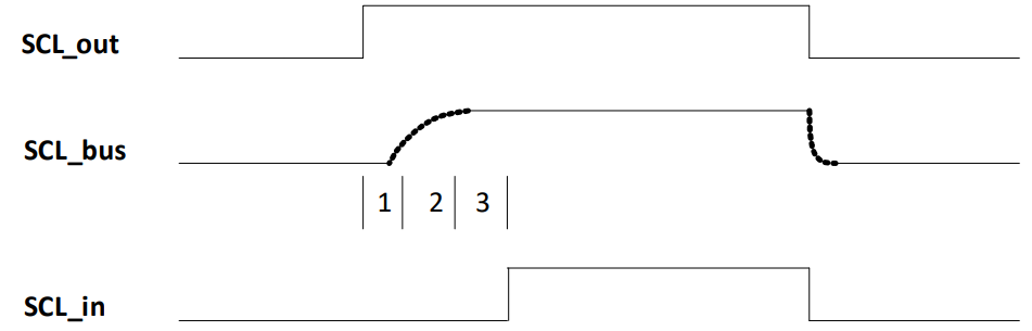
If the above three delays combined are greater than one clk_scb cycle, then the high phase of the SCL will be extended. This may cause the actual data rate on the I2C bus to be slower than expected. This can be avoided by:

Configure Interrupt

The interrupt is mandatory for I2C operation. The exception is the when only the Master Low-Level functions are used. The driver provides three interrupt functions: Cy_SCB_I2C_Interrupt, Cy_SCB_I2C_SlaveInterrupt, and Cy_SCB_I2C_MasterInterrupt. One of these functions must be called in the interrupt handler for the selected SCB instance. Call Cy_SCB_I2C_SlaveInterrupt when I2C is configured to operate as a slave, Cy_SCB_I2C_MasterInterrupt when I2C is configured to operate as a master and Cy_SCB_I2C_Interrupt when I2C is configured to operate as master and slave. Using the slave- or master-specific interrupt function allows reducing the flash consumed by the I2C driver. Also this interrupt must be enabled in the NVIC otherwise it will not work.

Note
The I2C driver documentation refers to the Cy_SCB_I2C_Interrupt function when interrupt processing is mandatory for the operation. This is done to simplify the readability of the driver's documentation. The application should call the slave- or master-specific interrupt functions Cy_SCB_I2C_SlaveInterrupt or Cy_SCB_I2C_MasterInterrupt, when appropriate.
void I2C_Isr(void)
{
Cy_SCB_I2C_Interrupt(SCB0, &i2cContext);
}
/* Assign I2C interrupt number and priority */
#define I2C_INTR_NUM scb_0_interrupt_IRQn
#define I2C_INTR_PRIORITY (3UL)
/* Populate configuration structure */
const cy_stc_sysint_t i2cIntrConfig =
{
.intrSrc = I2C_INTR_NUM,
.intrPriority = I2C_INTR_PRIORITY,
};
/* Hook interrupt service routine and enable interrupt */
(void) Cy_SysInt_Init(&i2cIntrConfig, &I2C_Isr);
NVIC_EnableIRQ(I2C_INTR_NUM);

Enable I2C

Finally, enable the I2C operation by calling Cy_SCB_I2C_Enable. Then I2C slave starts respond to the assigned address and I2C master ready to execute transfers.

/* Enable I2C to operate */
Cy_SCB_I2C_Enable(SCB0, &i2cContext);
/* Enable global interrupts */
__enable_irq();

Common Use Cases

Master Operation

The master API is divided into two categories: Master High-Level and Master Low-Level. Therefore, there are two methods for initiating I2C master transactions using either Low-Level or High-Level API. These two methods are described below. Only one method should be used at a time. They should not be mixed.

Use High-Level Functions

Call Cy_SCB_I2C_MasterRead or Cy_SCB_I2C_MasterWrite to communicate with the slave. These functions do not block and only start a transaction. After a transaction starts, the Cy_SCB_I2C_Interrupt handles further data transaction until its completion (successfully or with error occurring). To monitor the transaction, use Cy_SCB_I2C_MasterGetStatus or register callback function using Cy_SCB_I2C_RegisterEventCallback to be notified about I2C Callback Events.

uint8_t readBuffer [5UL];
uint8_t writeBuffer[2UL] = {0U, 5U};
/* Configure write transaction */
transfer.slaveAddress = 0x08U;
transfer.buffer = writeBuffer;
transfer.bufferSize = sizeof(writeBuffer);
transfer.xferPending = true; /* Do not generate Stop condition at the end of transaction */
/* Initiate write transaction.
* The Start condition is generated to begin this transaction.
*/
(void) Cy_SCB_I2C_MasterWrite(SCB0, &transfer, &i2cContext);
/* Wait for transaction completion */
while (0UL != (CY_SCB_I2C_MASTER_BUSY & Cy_SCB_I2C_MasterGetStatus(SCB0, &i2cContext)))
{
}
/* Configure read transaction */
transfer.buffer = readBuffer;
transfer.bufferSize = sizeof(readBuffer);
transfer.xferPending = false; /* Generate Stop condition the end of transaction */
/* Initiate read transaction.
* The ReStart condition is generated to begin this transaction because
* previous transaction was completed without Stop.
*/
(void) Cy_SCB_I2C_MasterRead(SCB0, &transfer, &i2cContext);
/* Wait for transaction completion */
while (0UL != (CY_SCB_I2C_MASTER_BUSY & Cy_SCB_I2C_MasterGetStatus(SCB0, &i2cContext)))
{
}
/* Process received data */

Use Low-Level Functions

Call Cy_SCB_I2C_MasterSendStart to generate a start, send an address with the Read/Write direction bit, and receive acknowledgment. After the address is ACKed by the slave, the transaction can be continued by calling Cy_SCB_I2C_MasterReadByte or Cy_SCB_I2C_MasterWriteByte depending on its direction. These functions handle one byte per call. Therefore, they should be called for each byte in the transaction. Note that for the Read transaction, the last byte must be NAKed. To complete the current transaction, call Cy_SCB_I2C_MasterSendStop or call Cy_SCB_I2C_MasterSendReStart to complete the current transaction and start a new one. Typically, do a restart to change the transaction direction without releasing the bus from the master control. The Low-Level functions are blocking and do not require calling Cy_SCB_I2C_Interrupt inside the interrupt handler. Using these functions requires extensive knowledge of the I2C protocol to execute transactions correctly.

Master Write Operation

/* Buffer to write to the slave */
uint8_t buffer[] = {0x55, 0x44, 0x33};
/* Wait 100 ms until operation completion */
uint32_t timeout = 100UL;
/* Send Start condition, address and receive ACK/NACK response from slave */
status = Cy_SCB_I2C_MasterSendStart(SCB0, 0x08U, CY_SCB_I2C_WRITE_XFER, timeout, &i2cContext);
if (CY_SCB_I2C_SUCCESS == status)
{
uint32_t cnt = 0UL;
/* Write data into the slave from the buffer */
do
{
/* Write byte and receive ACK/NACK response */
status = Cy_SCB_I2C_MasterWriteByte(SCB0, buffer[cnt], timeout, &i2cContext);
++cnt;
}
while((status == CY_SCB_I2C_SUCCESS) && (cnt < sizeof(buffer)));
}
/* Check status of transaction */
if ((status == CY_SCB_I2C_SUCCESS) ||
{
/* Send Stop condition on the bus */
status = Cy_SCB_I2C_MasterSendStop(SCB0, timeout, &i2cContext);
if (status == CY_SCB_I2C_SUCCESS)
{
/* Data has been written into the slave */
}
}
else
{
/* Other statuses do not require any actions */
}

Master Read Operation

/* Buffer to write to the slave */
uint8_t buffer[5U];
/* Wait 100 ms until operation completion */
uint32_t timeout = 100UL;
/* Send Start condition, address and receive ACK/NACK response from slave */
status = Cy_SCB_I2C_MasterSendStart(SCB0, 0x08U, CY_SCB_I2C_WRITE_XFER, timeout, &i2cContext);
if (CY_SCB_I2C_SUCCESS == status)
{
uint32_t cnt = 0UL;
/* Read data from the slave into the buffer */
do
{
if (cnt == (sizeof(buffer) - 1UL))
{
/* The last byte must be NACKed */
}
/* Read byte and generate ACK / or prepare for NACK */
status = Cy_SCB_I2C_MasterReadByte(SCB0, cmd, &buffer[cnt], timeout, &i2cContext);
++cnt;
}
while((status == CY_SCB_I2C_SUCCESS) && (cnt < sizeof(buffer)));
}
/* Check status of transaction */
if ((status == CY_SCB_I2C_SUCCESS) ||
{
/* Send Stop condition on the bus */
status = Cy_SCB_I2C_MasterSendStop(SCB0, timeout, &i2cContext);
if (status == CY_SCB_I2C_SUCCESS)
{
/* Process received data */
}
}
else
{
/* Other statuses do not require any actions.
* The received data should dropped.
*/
}

Slave Operation

Slave operation requires the Cy_SCB_I2C_Interrupt be called inside the interrupt handler. The read and write buffers must be provided for the slave to enable communication with the master. Use Cy_SCB_I2C_SlaveConfigReadBuf and Cy_SCB_I2C_SlaveConfigWriteBuf for this purpose. Note that after transaction completion the buffer must be configured again. Otherwise, the same buffer is used starting from the point where the master stopped a previous transaction. For example: The read buffer is configured to be 10 bytes and the master reads 8 bytes. If the read buffer is not configured again, the next master read will start from the 9th byte. To monitor the transaction status, use Cy_SCB_I2C_SlaveGetStatus or use Cy_SCB_I2C_RegisterEventCallback to register a callback function to be notified about I2C Callback Events.

Get Slave Events Notification

/* Register callback for event notification.
* It is better to do this during initialization before I2C is enabled.
*/
Cy_SCB_I2C_RegisterEventCallback(SCB0, I2C_SlaveEventHandler, &i2cContext);
/* Callback implementation */
void I2C_SlaveEventHandler(uint32_t events)
{
/* Slave sent data to master */
if (0UL != (events & CY_SCB_I2C_SLAVE_RD_CMPLT_EVENT))
{
if (0UL == (events & CY_SCB_I2C_SLAVE_ERR_EVENT))
{
/* Read complete without errors: update buffer content */
}
/* Setup read buffer for the next read transaction */
Cy_SCB_I2C_SlaveConfigReadBuf(SCB0, i2cReadBuffer, BUFFER_SIZE, &i2cContext);
}
/* Slave received data from master */
if (0UL != (events & CY_SCB_I2C_SLAVE_WR_CMPLT_EVENT))
{
if (0UL == (events & CY_SCB_I2C_SLAVE_ERR_EVENT))
{
/* Write complete without errors: process received data */
}
/* Setup buffer for the next write transaction */
Cy_SCB_I2C_SlaveConfigWriteBuf(SCB0, i2cWriteBuffer, BUFFER_SIZE, &i2cContext);
}
/* Ignore all other events */
}

Polling Slave Completion Events

/* Disable I2C Interrupt: protect code from interruption */
NVIC_DisableIRQ(I2C_INTR_NUM);
/* Check if write transaction completed */
if (0UL != (CY_SCB_I2C_SLAVE_WR_CMPLT & Cy_SCB_I2C_SlaveGetStatus(SCB0, &i2cContext)))
{
/* Process received data */
/* Configure buffer for the next write */
Cy_SCB_I2C_SlaveConfigWriteBuf(SCB0, i2cWriteBuffer, BUFFER_SIZE, &i2cContext);
/* Clear slave write status to capture following updates */
}
/* Enable I2C interrupt */
NVIC_EnableIRQ(I2C_INTR_NUM);

Slave Address Match Clock Stretching

/* Register callback for address match notification.
* It is better to do this during initialization before I2C is enabled.
*/
Cy_SCB_I2C_RegisterAddrCallback(SCB0, I2C_SlaveAddressHandler, &i2cContext);
/* Address match callback implementation */
cy_en_scb_i2c_command_t I2C_SlaveAddressHandler(uint32_t events)
{
/* Ignore events */
(void)events;
/* Set a user flag indicating ACK is pending. */
i2cAckPending = true;
/* Implement application specific logic here to return ACK/NACK/WAIT command. */
/* Return i2c command. */
return i2cCmd;
}

Function Cy_SCB_I2C_SlaveSendAckNack() should be called by the user application if CY_SCB_I2C_WAIT is returned by the address match callback.

/* An example of a user application function to send ACK/NACK command. */
void I2C_SlaveSendAckNack(bool ackNack)
{
if(i2cAckPending == true)
{
/* Clear ACK pending flag. */
i2cAckPending = false;
/* Send Ack/Nack */
Cy_SCB_I2C_SlaveSendAckNack(SCB0, ackNack, &i2cContext);
}
}
Note
All slave API (except Cy_SCB_I2C_SlaveAbortRead and Cy_SCB_I2C_SlaveAbortWrite) are not interrupt-protected and to prevent a race condition, they should be protected from the I2C interruption in the place where they are called. The code snippet Polling Slave Completion Events above shows how to prevent a race condition when detect transfer completion and update I2C slave write buffer. The simple example of race condition is: application updates slave read buffer the I2C master starts read transfer. The I2C interrupts read buffer update and I2C interrupt loads current read buffer content in the TX FIFO . After I2C interrupt returns the application updates remaining part of the read buffer. As a result the mater read partly updated buffer.

High-speed mode

High-speed mode supports data rates up to 3.4Mbps in Slave mode only. Set up the I2C driver for High-speed transfer is similar to base I2C configuration Configure I2C. There are only two differences: hsEnable and useRxFifo must be enabled.

/* High-speed slave configuration */
const cy_stc_scb_i2c_config_t i2cConfig =
{
.useRxFifo = true, /* Always must be enabled in High-speed mode */
.useTxFifo = true,
.slaveAddress = 0x10U,
.slaveAddressMask = 0xF0U,
.acceptAddrInFifo = false,
.ackGeneralAddr = false,
.hsEnable = true,
.enableWakeFromSleep = false,
.enableDigitalFilter = false,
.lowPhaseDutyCycle = 0U,
.highPhaseDutyCycle = 0U,
};
/* Configure I2C to operate */
(void) Cy_SCB_I2C_Init(SCB0, &i2cConfig, &i2cContext);

After initialization and before block enabling need to register High-speed callback High-speed Callback.

Note
High-speed mode is only applicable for Slave mode.
The address callback is not available in High-speed mode.
High-speed mode is only applicable for PSoC 4100S Max.

High-speed Callback

For proper operation, in High-speed mode, create a callback function and register it by Cy_SCB_I2C_RegisterHsModeCallback. The callback function changes clk_scb before entering to High-speed mode and after exiting it to support necessary data rate I2C High-speed mode Callback Events.

The callback function can be generated by using the Device Configurator.

/* Register callback.
* It is better to do this during initialization before I2C is enabled.
*/
/* Number of Peripherals Clock Divider */
#define I2C_CLK_DIV_NUMBER (0U)
/* Callback implementation */
void I2C_HsCallback(uint32_t event)
{
/* Slave enter to High-speed mode */
{
/* The I2C slave desired data rate in High-speed mode is 3.4 Mbps.
* To support this data rate, the clk_scb frequency must be in range 41.01 – 48 MHz.
* Find clk_scb valid ranges in the TRM section I2C sub-section Oversampling and Bit Rate.
* For clk_hf = 48 MHz, select divider value 0 and get clk_scb = (48 MHz / 1) = 48 MHz.
* This clock frequency meets the above described requirements. */
}
/* Slave exit from High-speed mode */
{
/* The I2C slave desired data rate is 400 kbps.
* To support this data rate, the clk_scb frequency must be in range 7.82 – 15.38 MHz.
* Find clk_scb valid ranges in the TRM section I2C sub-section Oversampling and Bit Rate.
* For clk_hf = 48 MHz, select divider value 3 and get clk_scb = (48 MHz / 4) = 12 MHz.
* This clock frequency meets the above described requirements. */
}
}

Refer to the technical reference manual (TRM) section I2C sub-section Oversampling and Bit Rate to get information how to configure I2C to run with the desired data rate.

Low Power Support

The I2C driver provides callback functions to handle power mode transition. The callback Cy_SCB_I2C_DeepSleepCallback must be called during execution of Cy_SysPm_CpuEnterDeepSleep. To trigger the callback execution, the callback must be registered before calling the power mode transition function. Refer to SysPm (System Power Management) driver for more information about power mode transitions and callback registration.

Warning
The current version doesn't support the wake up from Deep-sleep by High-speed transfer.

Deep Sleep Clock Config Callback

For proper operation, when the I2C slave is configured to be a wakeup source from Deep Sleep mode, create a callback function and register it by Cy_SCB_EZI2C_RegisterDSClockConfig.

The callback function can be generated by using the Device Configurator.

/* Register callback.
* It is better to do this during initialization before I2C is enabled.
*/
Cy_SCB_I2C_RegisterDSClockConfig(SCB0, I2C_DsClockConfigCallback, &i2cContext);
/* Number of Peripherals Clock Divider */
#define I2C_CLK_DIV_NUMBER (0U)
/* Callback implementation */
void I2C_DsClockConfigCallback(uint32_t event)
{
/* Transition into deep sleep mode */
{
/* Disable SCB clock */
}
/* Wake up from deep sleep mode */
{
/* Enable SCB clock */
}
}
Note
Not applicable for PSoC 4100S Max and PSoC 4000T.