Driver API for PWM.
The functions and other declarations used in this part of the driver are in cy_tcpwm_pwm.h. You can also include cy_pdl.h to get access to all functions and declarations in the PDL.
Use PWM mode when an output square wave is needed with a specific period and duty cycle, such as:
- Creating arbitrary square wave outputs
- Driving an LED (changing the brightness)
- Driving Motors (dead time assertion available)
The PWM has the following features:
- 16- or 32-bit Counter.
- Two Programmable Period registers that can be swapped.
- Two Output Compare registers that can be swapped on overflow and/or underflow.
- Left Aligned, Right Aligned, Center Aligned, and Asymmetric Aligned modes
- Continuous or One Shot run modes.
- Pseudo Random mode.
- Two PWM outputs with Dead Time insertion, and programmable polarity.
- Interrupt on Terminal Count and Compare or Capture 0. Interrupt on Compare or Capture 1 is only available in TCPWM Version 2.
- Start, Reload, Stop, Swap (Capture), and Count Inputs.
- Immediate Kill, Kill 0 Input, Kill 1 Input, PWM output on Disable, PWM outputs, PWM Dead Time Clocks, Taps Enabled. All these features are only available in TCPWM Version 2.
- Multiple Components can be synchronized together for applications. such as three phase motor control.
- Two programmable trigger outputs, trig_out0 and trig_out1 that generate a trigger on one of the following events Overflow, Underflow, Terminal Count, Compare Match 0/1, and PWM output. The available triggers are dependent on the PWM mode. All these features are only available in TCPWM Version 2.
- Overflow, Underflow, and Compare(cc_match) trigger outputs are only available in TCPWM Version 1.
- Second Compare Match (CC_MATCH1) event is only available in TCPWM Version 2.
Configuration Considerations
The PWM configuration can be divided to number of sequential steps listed below:
Configure PWM
To configure PWM, provide the configuration parameters in the cy_stc_tcpwm_pwm_config_t structure. The Configuration structure can be modified through software, but if the configurator in ModusToolbox is used then the configuration structure will be updated with the users input. To initialize the driver, call Cy_TCPWM_PWM_Init function providing a pointer to the populated cy_stc_tcpwm_pwm_config_t structure.
For TCPWM V1 Configuration
{
0UL,
99UL,
199UL,
true,
33UL,
66UL,
true,
0UL,
0UL,
false,
};
#define MY_TCPWM_PWM_NUM (0UL)
#define MY_TCPWM_PWM_MASK (1UL << MY_TCPWM_PWM_NUM)
{
}
For TCPWM V2 Configuration
{
0UL,
99UL,
199UL,
true,
33UL,
66UL,
true,
0UL,
0UL,
false,
false,
0x00UL,
33UL,
66UL,
true,
true,
true,
true,
true,
true,
5U,
#if defined (CY_IP_MXS40TCPWM)
1UL,
#endif
};
#define MY_TCPWM_PWM_NUM (0UL)
#define MY_TCPWM_PWM_MASK (1UL << MY_TCPWM_PWM_NUM)
{
}
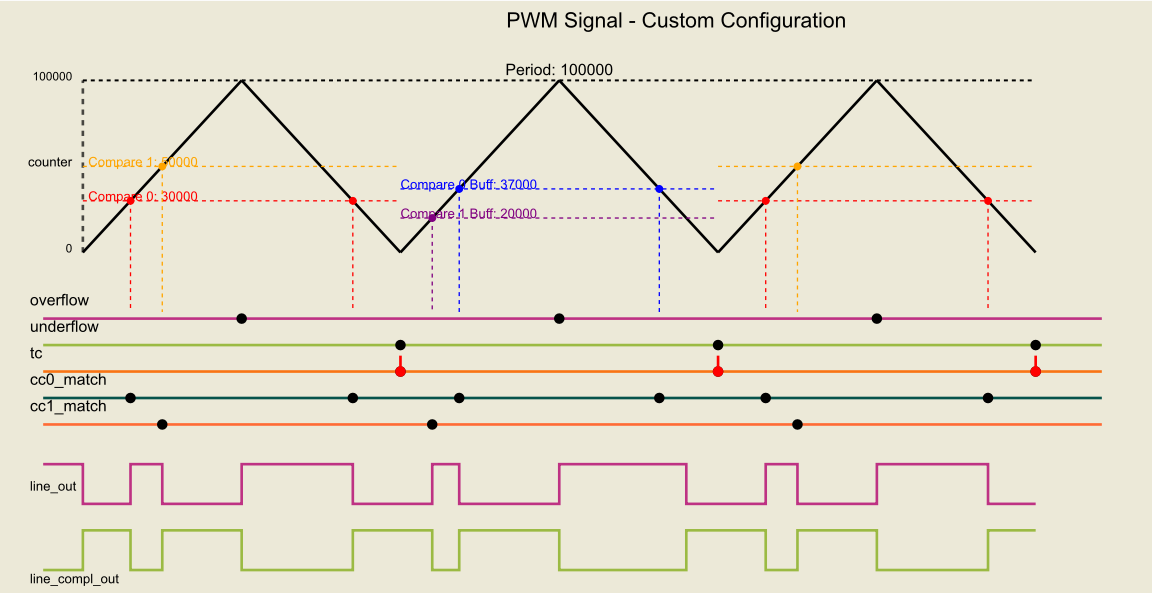
Configure Custom Aligned PWM
Set cy_stc_tcpwm_pwm_config_t::pwmAlignment to CY_TCPWM_PWM_CUSTOM_ALIGN to build a non-standard waveform. The predefined alignments (Left, Right, Center, Asymmetric, ...) preset the counter direction, the initial counter value and the per-event line actions for you. The custom alignment instead lets you program those CTRL, COUNTER and TR_PWM_CTRL register fields explicitly. It is available only on the MXS40 TCPWM IP.
The following members of cy_stc_tcpwm_pwm_config_t are consumed only when cy_stc_tcpwm_pwm_config_t::pwmAlignment is CY_TCPWM_PWM_CUSTOM_ALIGN, as listed below:
Each of the four action members takes a PWM CC Match / Overflow / Underflow Actions value (Set, Clear, Invert or No Change) applied to line_out (and inverted onto line_compl_out) when the corresponding event occurs. Together, the counter direction, the initial value and the four event actions fully define the output waveform.
The same fields can also be changed at run time (after Cy_TCPWM_PWM_Init) with the dedicated setters, each performing a single read-modify-write of its CTRL / TR_PWM_CTRL field:
{
.period0 = 99UL,
.compare0 = 25UL,
.compare1 = 75UL,
.initialCountVal = 0UL,
};
#define MY_CUSTOM_PWM_NUM (0UL)
{
}
In the ModusToolbox Device Configurator, select Custom in the PWM Configurations drop-down of the PWM signal behavior group to unlock the Count Direction, Initial Counter Value and the CC0 / CC1 Match Action and Overflow / Underflow Action fields.
Custom PWM signal behavior configuration
How each custom parameter shapes the output waveform:
- Count Direction (cy_stc_tcpwm_pwm_config_t::countDirectionMode) - defines the counting scheme and therefore which events fire and where the compare matches land on the ramp. Count Up ramps 0 -> PERIOD and generates only overflow; Count Down ramps PERIOD -> 0 and generates only underflow; the Up/Down modes ramp up then down, producing both an overflow (at PERIOD) and an underflow (at 0) and hitting each compare value twice per period. It also selects when the terminal count (TC) is issued (on underflow only, or on both overflow and underflow).
- Initial Counter Value (cy_stc_tcpwm_pwm_config_t::initialCountVal) - the value loaded into the counter at start. It sets the phase/starting point of the very first period (for example, starting at 0 for up-counting, at PERIOD for down-counting, or at 1 for up/down-counting) and thus the initial output level before the first match occurs.
- CC0 Match Action (cy_stc_tcpwm_pwm_config_t::cc0MatchMode) - the action applied to line_out (and inverted onto line_compl_out) when COUNTER equals Compare 0. This is normally the edge that starts or ends the pulse (one of the two duty-cycle edges).
- CC1 Match Action (cy_stc_tcpwm_pwm_config_t::cc1MatchMode) - the action applied when COUNTER equals Compare 1, giving an independent second edge so the pulse can be bounded by two arbitrary compare values (CC0 and CC1) rather than by a compare and a period boundary. Effective only on counters that provide a CC1 register; ignored otherwise.
- Overflow Action (cy_stc_tcpwm_pwm_config_t::overflowMode) - the action taken when the counter reaches PERIOD (overflow). Use it to force a known output level at the top of the ramp / period boundary (for example, re-arming the line high or low at the start of each period).
- Underflow Action (cy_stc_tcpwm_pwm_config_t::underflowMode) - the action taken when the counter reaches 0 (underflow). Use it to force a known output level at the bottom of the ramp, which is what shapes the waveform in Count Down and Up/Down modes.
Each action is one of PWM CC Match / Overflow / Underflow Actions - Set drives line_out to 1, Clear drives it to 0, Invert toggles it (useful for center-style waveforms), and No Change leaves it untouched so that event has no effect on the output. Choosing conflicting or overlapping actions (for example a match and an overflow on the same tick) lets you build non-standard waveforms that the predefined alignments cannot express.
Assign Clock Divider
The clock source must be connected to proper working. Any of the peripheral clock dividers could be used. Use the SysClk (System Clock) driver API to do that.
Enable PWM
PWM has to be enabled before starting
#define MY_TCPWM_PWM_NUM (0UL)
Start PWM
PWM has to be started
#define MY_TCPWM_PWM_NUM (0UL)