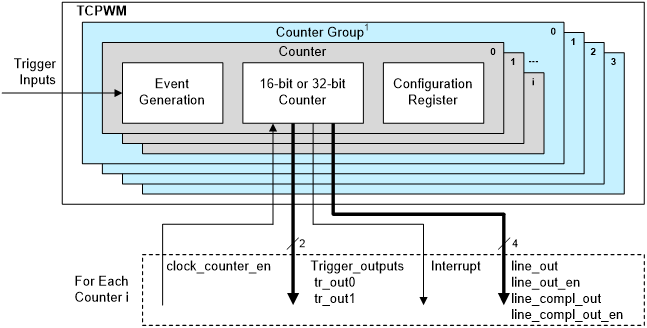
The TCPWM driver is a multifunction driver that implements Timer Counter, PWM, Quadrature Decoder, Shift Register and Motion Interface functionality using the TCPWM block.
The functions and other declarations used in this driver are in cy_tcpwm_counter.h, cy_tcpwm_pwm.h, cy_tcpwm_quaddec.h, cy_tcpwm_shiftreg.h, cy_tcpwm_motif.h respectively. Include cy_pdl.h to get access to all functions and declarations in the PDL.
Each TCPWM block is a collection of counters that can all be triggered simultaneously. For each function call, the base register address of the TCPWM being used must be passed first, followed by the index of the counter you want to touch next.
The TCPWM supports eight function modes:
- Timer
- Capture
- Quadrature Decoder
- Pulse Width Modulation (PWM)
- PWM with dead time insertion (PWMDT)
- Pseudo random PWM (PWMPR)
- Shift Register
- Motion Interface (MOTIF)
The TCPWM driver is structured to map these seven functional modes to four high level operating modes:
- Timer/Counter (includes Timer, Capture modes)
- PWM (PWM, PWMDT, PWMPR)
- Quadrature Decoder
- Shift Register
- MOTIF
A brief description on each of the operating modes:
Timer/Counter
Use this mode whenever a specific timing interval or measurement is needed. Examples include:
- Creating a periodic interrupt for running other system tasks
- Measuring frequency of an input signal
- Measuring pulse width of an input signal
- Measuring time between two external events
- Counting events
- Triggering other system resources after x number events
- Capturing time stamps when events occur
PWM
Use this mode when an output square wave is needed with a specific period and duty cycle, such as:
- Creating arbitrary square wave outputs
- Driving an LED (changing the brightness)
- Driving Motors (dead time assertion available)
Quadrature Decoder
A quadrature decoder is used to decode the output of a quadrature encoder. A quadrature encoder senses the position, velocity, and direction of an object (for example a rotating axle, or a spinning mouse ball). A quadrature decoder can also be used for precision measurement of speed, acceleration, and position of a motor's rotor, or with a rotary switch to determine user input.
Shift Register
Shift Register functionality shifts the counter value to the right. A shift register is used to apply a signal delay function which can be used eg: in detecting frequency shift keying (FSK) signals. A shift register is also used in parallel-in to serial-out data conversion and serial-in to parallel-out data conversion.
TCPWM Versions
There are three versions of TCPWM driver
TCPWM Version 3
- The mxtcpwm.3.0 consists of up to 2048, 16-bit or 32-bit counters
- Counter groups up to 8*256
- Counter compare, period, line_sel and dead time registers are double buffered.
- Parallel data path support for CC0/CC1 register through dedicated data interface (only applicable to mxtcpwm 3.1, PSOC C3 do not support this)
- Glitch Filter with configurable depth supported on General-purpose triggers used by all counters and specific one-to-one triggers for each counter
- Shadow registers available for duty, period, dead time, signal and polarity
- Enhanced shadow update mechanism
- Independent control of clock pre-scalar and dead time
- Configurable PWM dithering on period as well as duty cycle
- Configurable option to continue / pause with the ability to enter passive state through kill polarity in debug mode
- Output state control for PWM signal during stop or kill operation synchronous to period match
- Independent line polarity setting for PWM signal during kill operation
- Support up to 4 Motion Interface (MOTIF)
- Support interrupt output for each MOTIF
- Hall interface for direct connection to Hall sensors
- HW look-up table for advance motor control feedback loop operation
- Synchronous modulation support for multiple counters
- Support HRPWM (High resolution PWM generation) feature in both 16-bit and 32-bit TCPWM counters (Only applicable to mxtcpwm 3.1, PSOC C3 only has 4 HRPWM blocks on the 32 bit PWMs.)
- HRPWM enhancements are limited to PWM and PWM_DT mode only
- HRPWM consists of an analog interpolator (also referred as delay element)
- Analog interpolator consists of delay elements which uses the input clock to generate a set of delayed phases. These delayed phases are then used to delay the edges of the incoming PWM from tcpwm.
- Analog interpolator is used to shift the edges of line_out and line_compl_out coming as output from the TCPWM to the analog interpolator.
- The LSBs are used for fractional or micro ticks for delaying the line_out and line_compl_out outputs for PERIOD/PERIOD_BUFF, CC0/CC0_BUFF, and CC1/CC1_BUFF and DT/DT_BUFF.
- Number of LSB bits used for fractional control is control by the design time parameter, GRP_HRPWM_WIDTH.
- The remaining bits given by [GRP_CNT_WIDTH-1:GRP_HRPWM_WIDTH] are used by the mxtcpwm counter.
TCPWM Version 2
- Devices CY8C61x4 and CY8C62x4 use this version.
- Supports up to four counter groups (check TRM for actual number of groups supported)
- Each counter group consists of up to 256 counters (check TRM for actual number of counters supported)
- Each counter
- Can run in one of seven function modes
- Supports various counting modes:
- One-shot mode, Continuous mode (Up/Down/Up-down)
- Selects input signals
- Start, Reload, Stop, Count, and two Capture event signals
- Generates output signals:
- Two output triggers, PWM output, and Interrupt
- Trigger Outputs (TR_OUT0/1) and an Interrupt on an event
- Overflow (OV)
- Underflow (UN)
- Terminal Count (TC)
- CC0/1_MATCH
- LINE_OUT
- Supports debug mode
- Each counter can produce two output signals

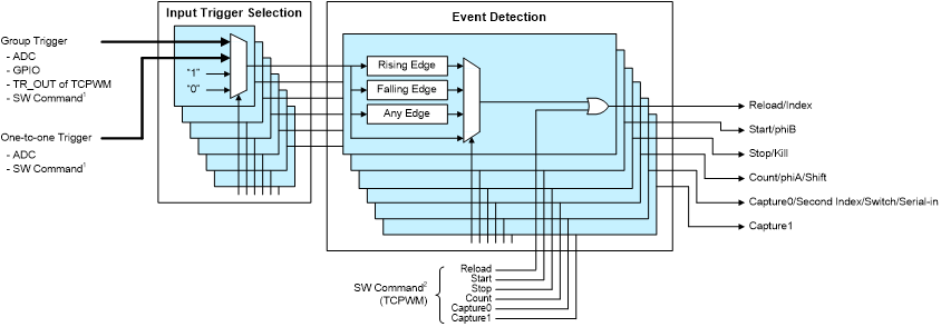
- Input Trigger Selection and Event Detection
- The counter control signals are generated as follows:
- Selects input signals from two types of trigger multiplexer signals
- Group trigger and one-to-one trigger
- The constant '1' and '0' are also used as input triggers
- Detects the selected edge from four types
- Rising edge/falling edge/any edge/no edge
- Supports software (SW) command
- SW command of Trigger Multiplexer/SW command of TCPWM
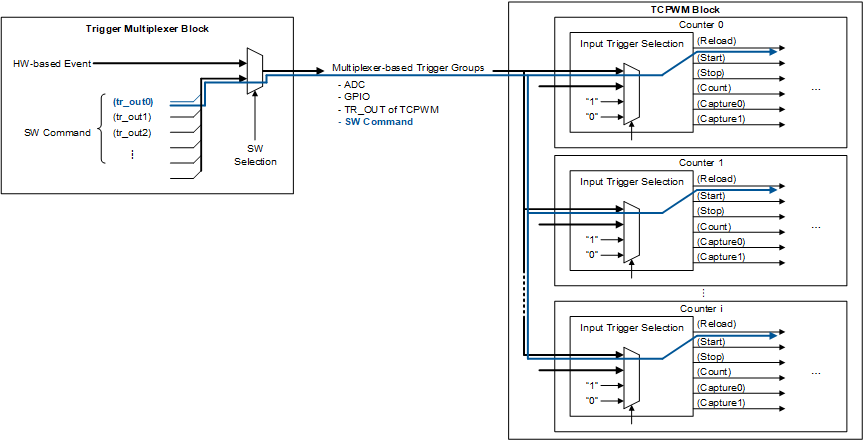
- Simultaneous Activation:
- When a Trigger Multiplexer block SW command is used, the TCPWM counters can be activated at the same time
TCPWM Version 1
- Devices CY8C61x6, CY8C61x7, CY8C62x5, CY8C62x6, CY8C62x7, CY8C62x8, CY8C62xA, CY8C63x6, CY8C63x7, CYS0644xxZI-S2D44, CYB0644xxZI-S4D44, CYB06447BZI-BLDX, CYB06447BZI-D54 and CYB06445LQI-S3D42 use this version.
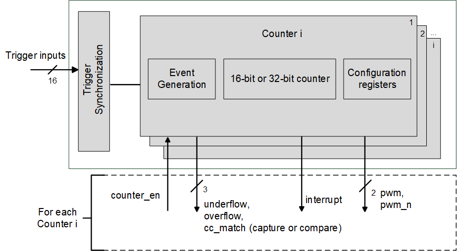
- Supports up to 32 counters (check TRM for actual number of counters supported)
- Synchronized operation of multiple counters.
- 16 or 32 bit counter, compare/capture (CC) and period registers.
- CC and period registers are double buffered.
- Up, down and up/down counting modes.
- 14 trigger input signals and 2 constant input signals: '0' and '1', for a total of 16 hardware (HW) input signals
- Rising edge, falling edge, combined rising/falling edge detection or pass-through on all HW input signals to derive counter events.
- The start, reload, stop and capture events can be generated by software.
- Clock pre-scaling (1x, 2x, 4x ... 128x).
- Support Pseudo Random PWM
- 3 output trigger signals for each counter to indicate underflow, overflow and cc_match events.
- 2 PWM complementary output lines for each counter. Dead time insertion ([0, 255] counter cycles).
- Support one interrupt output for each counter.

- Many functions work with an individual counter. You can also manage multiple counters simultaneously for certain functions.
- These are listed in the Functions section of the TCPWM.
- You can enable, disable, or trigger (in various ways) multiple counters simultaneously.
- For these functions you provide a bit field representing each counter in the TCPWM you want to control.
- You can represent the bit field as an ORed mask of each counter, like ((1U << cntNumX) | (1U << cntNumX) | (1U << cntNumX)), where X is the counter number from 0 to 31.
- Note
-
More Information
For more information on the TCPWM peripheral, refer to the technical reference manual (TRM).
Changelog
| Version | Changes | Reason for Change |
| 1.90 | Added new parameters to cy_stc_tcpwm_pwm_config_t structure. | Enhancements for Debug Freeze feature configuration. |
| 1.80 | Newly added Motion Interface (MOTIF) functionality. | Added the new Motion Interface for the PSOC C3 (CAT1B) device. |
Updated the following APIs:
Newly added APIs:
| Bug fixing and HRPWM enhancements. |
| 1.70 | Newly added enum cy_en_copy_swap_config_t.
| Supported Glitch filter with configurable depth, HW look-up table for advance motor control, bug fixes and enhancement in reload and swap functionality. |
Newly added APIs :
Updated the following APIs:
Newly added and updated enums:
| Support for line select, HRPWM enhancements, enhancement in DT BUFF and SWAP ENABLE handling. |
| 1.60 | Newly Added Cy_TCPWM_OutputTriggerSetup API and code enhancement. | Glitch filter support added for TCPWM version 3 and above. |
| 1.50 |
|
-
Support for IP version 3.0.
-
Bug fixes.
-
Documentation update.
|
| 1.40 | Support for CAT1B and CAT1D devices is added. No changes in public APIs interface and behavior. | New devices support added. |
| 1.30.1 | Updated documentation of PWM mode. | Documentation enhancement. |
| 1.30 | Added new option to Swap Overflow/Underflow behavior in PWM Centre/Asymmetric Alignment modes. | New feature. |
| 1.20 | Added new features: Shift Register, New QuadDec modes, Additional Compare/Capture Buffer. | New silicon family support. |
| 1.10.2 | Minor documentation updates. | Documentation enhancement. |
| 1.10.1 | Added header guards CY_IP_MXTCPWM. | To enable the PDL compilation with wounded out IP blocks. |
| 1.10 | Flattened the organization of the driver source code into the single source directory and the single include directory. | Driver library directory-structure simplification. |
| Added register access layer. Use register access macros instead of direct register access using dereferenced pointers. | Makes register access device-independent, so that the PDL does not need to be recompiled for each supported part number. |
| 1.0.1 | Added a deviation to the MISRA Compliance section. Added function-level code snippets. | Documentation update and clarification |
| 1.0 | Initial version | |


