This driver provides API functions to configure, manage and interact with the Autonomous Controller (AC) subsystem within High Performance Programmable Analog Sub-System (HPPASS).
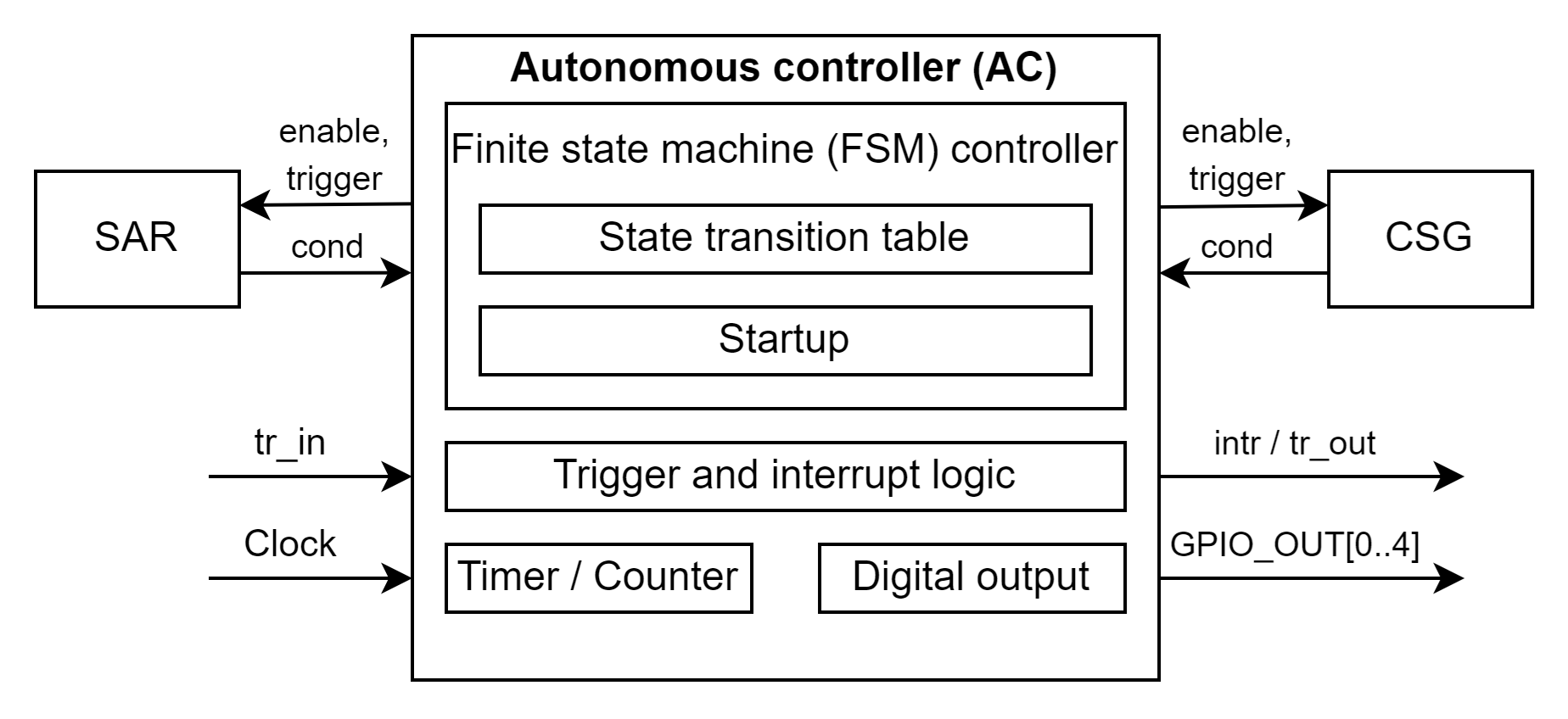
The autonomous controller is a programmable finite-state machine (FSM) sequencer that works from a 16-entry state transition table, to transition appropriately through various pre-defined states, based on timer, counter, and/or events. The AC provides hardware control without the need for CPU or external intervention.
The internal structure and external HW interface of the AC is shown at the picture below.
Autonomous controller can perform the following functions:
- Enable/disable SAR ADC and/or CSG, provide a BLOCK_READY status to the firmware
- Process input hardware/firmware triggers to execute programmed actions
- Trigger any of the internal or connected blocks
- Implement hardware delays/counters
- Perform periodic actions (e.g., triggering) in a timed loop
- Receive conditions from the connected blocks and acting on those events
- Generate an AC-based interrupt to the CPU
- Digital output to as many as five GPIOs
The AC has a standard interface to each sub-block of HPPASS, the interface consists of: Enable, Trigger, and Conditions signals groups.
Refer to the Technical Reference Manual for detailed information.
To configure the AC, the driver uses a configuration structure of type cy_stc_hppass_ac_t that must be predefined. In turn, this structure holds the non-NULL pointer to the State Transition Table (STT) array of type cy_stc_hppass_ac_stt_t. The configuration structure also holds a specialized startup configuration array of type cy_stc_hppass_startup_t.
This array defines the parameters of the AC HW startup.
State Transition Table
The AC can implement a single threaded programming sequence using a simple format. The AC program is stored in a RAM table called a STT, which consists of 16 States (or programming instructions) of type cy_stc_hppass_ac_stt_t. These programming instructions can form one or more programs, called by FW, like subroutines.
- Note
- At least one state (e.g. 'Stop') of the state transition table must be predefined in the STT.
-
The CSG and/or SAR should be enabled in the first state of the STT to ensure proper working of the AC.
Here is an example of a simple program coded by STT instructions.
#define CY_HPPASS_STT_NUM_ENTRIES (4U)
{
{
.branchStateIdx = 0U,
.interrupt = false,
.count = 199U,
.gpioOutUnlock = true,
.csgUnlock = {false, false, false, false, false},
.csgEnable = {false, false, false, false, false},
.csgDacTrig = {false, false, false, false, false},
.sarUnlock = false,
.sarEnable = false,
.sarGrpMsk = 0U,
.sarMux = {{0}, {0}, {0}, {0}}
},
{
.branchStateIdx = 0U,
.interrupt = false,
.count = 199U,
.gpioOutUnlock = true,
.gpioOutMsk = MY_HPPASS_GPIO_OUT_DISABLE_ALL,
.csgUnlock = {false, false, false, false, false},
.csgEnable = {false, false, false, false, false},
.csgDacTrig = {false, false, false, false, false},
.sarUnlock = false,
.sarEnable = false,
.sarGrpMsk = 0U,
.sarMux = {{0}, {0}, {0}, {0}}
},
{
.branchStateIdx = 0U,
.interrupt = false,
.count = 0U,
.gpioOutUnlock = false,
.gpioOutMsk = MY_HPPASS_GPIO_OUT_DISABLE_ALL,
.csgUnlock = {false, false, false, false, false},
.csgEnable = {false, false, false, false, false},
.csgDacTrig = {false, false, false, false, false},
.sarUnlock = false,
.sarEnable = false,
.sarGrpMsk = 0U,
.sarMux = {{0}, {0}, {0}, {0}}
}
};
Startup
Startup is initiated by enabling the AC with loaded AC startup sequence instructions (cy_stc_hppass_ac_t::startup). The startup block have dedicated logic to time the HPPASS startup and will generate BLOCK_READY condition once HPPASS startup is done. The application should wait for the BLOCK_READY condition before using any HPPASS features. The BLOCK_READY condition can be checked by Cy_HPPASS_AC_IsBlockReady function.
- Note
- Only usage of the startup parameters recommended by the vendor guarantees the reliable work of the autonomous controller.
Please use the Device Configurator tool to make configurations or refer to the Technical Reference Manual chapter 27.2.1.1 for detailed information.
Code Snippets
Snippet 1: GPIO Toggling by Autonomous Controller
An example is shown below, describes a simple case of usage Autonomous Controller for toggling GPIO Out:
- Configure GPIO pin P7_0 and set HSIOM mode as P7_0_PASS_MCPASS_DOUT0:
{
.hsiom = P7_0_PASS_MCPASS_DOUT0,
.intMask = 0UL,
.vregEn = 0UL,
.ibufMode = 0UL,
.vtripSel = 0UL,
.vrefSel = 0UL,
.vohSel = 0UL,
.nonSec = 0UL
};
- Configure cy_stc_hppass_ac_stt_t structure array with appropriate configurations for each state of Autonomous Controller:
#define CY_HPPASS_STT_NUM_ENTRIES (4U)
{
{
.branchStateIdx = 0U,
.interrupt = false,
.count = 199U,
.gpioOutUnlock = true,
.csgUnlock = {false, false, false, false, false},
.csgEnable = {false, false, false, false, false},
.csgDacTrig = {false, false, false, false, false},
.sarUnlock = false,
.sarEnable = false,
.sarGrpMsk = 0U,
.sarMux = {{0}, {0}, {0}, {0}}
},
{
.branchStateIdx = 0U,
.interrupt = false,
.count = 199U,
.gpioOutUnlock = true,
.csgUnlock = {false, false, false, false, false},
.csgEnable = {false, false, false, false, false},
.csgDacTrig = {false, false, false, false, false},
.sarUnlock = false,
.sarEnable = false,
.sarGrpMsk = 0U,
.sarMux = {{0}, {0}, {0}, {0}}
},
{
.branchStateIdx = 0U,
.interrupt = false,
.count = 199U,
.gpioOutUnlock = true,
.gpioOutMsk = MY_HPPASS_GPIO_OUT_DISABLE_ALL,
.csgUnlock = {false, false, false, false, false},
.csgEnable = {false, false, false, false, false},
.csgDacTrig = {false, false, false, false, false},
.sarUnlock = false,
.sarEnable = false,
.sarGrpMsk = 0U,
.sarMux = {{0}, {0}, {0}, {0}}
},
{
.branchStateIdx = 0U,
.interrupt = false,
.count = 0U,
.gpioOutUnlock = false,
.gpioOutMsk = MY_HPPASS_GPIO_OUT_DISABLE_ALL,
.csgUnlock = {false, false, false, false, false},
.csgEnable = {false, false, false, false, false},
.csgDacTrig = {false, false, false, false, false},
.sarUnlock = false,
.sarEnable = false,
.sarGrpMsk = 0U,
.sarMux = {{0}, {0}, {0}, {0}}
}
};
- Set HPPASS and AC state transition table configuration, used by Cy_HPPASS_Init API:
{
{
.stt = stt_cfg,
.startupClkDiv = 7U,
.startup = {{0}, {0}, {0}, {0}}
},
.vref = CY_HPPASS_VREF_LOCAL,
.csg = NULL,
.sar = NULL,
.trigIn = {{0}, {0}, {0}, {0}, {0}, {0}, {0}, {0}},
.trigLevel = {{0}, {0}, {0}, {0}, {0}, {0}, {0}, {0}}
};
- Initialize and start Autonomous Controller:
Snippet 2: The AC state triggering by FW and HW input triggers
The below example is a simple case of using HPPASS input trigger events to trigger the Autonomous Controller state. The code snippet shows two approaches: FW trigger and HW trigger configurations.
- Configure the cy_stc_hppass_ac_stt_t structure array, where the Autonomous Controller in state #0 waits for a trigger to change that state:
#define CY_HPPASS_STT_NUM_ENTRIES (4U)
{
{
.branchStateIdx = 0U,
.interrupt = false,
.count = 0U,
.gpioOutUnlock = false,
.gpioOutMsk = 0,
.csgUnlock = {false, false, false, false, false},
.csgEnable = {false, false, false, false, false},
.csgDacTrig = {false, false, false, false, false},
.sarUnlock = true,
.sarEnable = true,
.sarGrpMsk = 0U,
.sarMux = {{0}, {0}, {0}, {0}}
},
{
.branchStateIdx = 0U,
.interrupt = false,
.count = 0U,
.gpioOutUnlock = false,
.gpioOutMsk = 0,
.csgUnlock = {false, false, false, false, false},
.csgEnable = {false, false, false, false, false},
.csgDacTrig = {false, false, false, false, false},
.sarUnlock = false,
.sarEnable = false,
.sarGrpMsk = 0U,
.sarMux = {{0}, {0}, {0}, {0}}
}
};
{
{
.stt = stateTransitionTable,
.gpioOutEnMsk = 0U,
.startupClkDiv = 7U,
.startup = {{0}, {0}, {0}, {0}}
},
.vref = CY_HPPASS_VREF_LOCAL,
.csg = NULL,
.sar = NULL,
.trigIn =
{
{
},
{
},
{0}, {0}, {0}, {0}, {0}, {0}
},
.trigLevel = {{0}, {0}, {0}, {0}, {0}, {0}, {0}, {0}}
};
printf("Cy_TCPWM_Counter_Init status: %s\r\n", ((tcpwmStatus == 0) ? "SUCCESS" : "FAIL"));
trigmuxStatus =
Cy_TrigMux_Select(TRIG_OUT_1TO1_2_TCPWM0_GRP0_CNT3_OUT1_TO_MCPASS_TR_IN1, 0, TRIGGER_TYPE_EDGE);
printf("Cy_TrigMux_Select status: %s\r\n", ((trigmuxStatus == 0) ? "SUCCESS" : "FAIL"));
printf("Cy_HPPASS_Init status: %s\r\n", ((hppassStatus == 0) ? "SUCCESS" : "FAIL"));
printf("Cy_HPPASS_AC_Start status: %s\r\n", ((hppassACStatus == 0) ? "SUCCESS" : "FAIL"));
__enable_irq();
printf("\nAC state: %s, STT pointer = %d, Ready to testing\r\n", ((hppassState.ac.running == 0) ? "STOPPED" : "RUNNING"), hppassState.ac.stateIdx);
for(uint8_t i=1; i<=2; i++)
{
printf("--- Start FW Trigger test ---\r\n");
printf("AC state: %s, STT pointer = %d, ", ((hppassState.ac.running == 0) ? "STOPPED" : "RUNNING"), hppassState.ac.stateIdx);
printf("The test: %s\r\n", (((hppassState.ac.running == 1) && (hppassState.ac.stateIdx == i)) ? "PASSED" : "FAILED"));
}
printf("--- Start HW Trigger test ---\r\n");
printf("AC state: %s, STT pointer = %d, ", ((hppassState.ac.running == 0) ? "STOPPED" : "RUNNING"), hppassState.ac.stateIdx);
printf("The test: %s\r\n", (((hppassState.ac.running == 0) && (hppassState.ac.stateIdx == 3)) ? "PASSED" : "FAILED"));