The SPI-based communication interface to the external quad SPI (QSPI) high-speed memory devices.
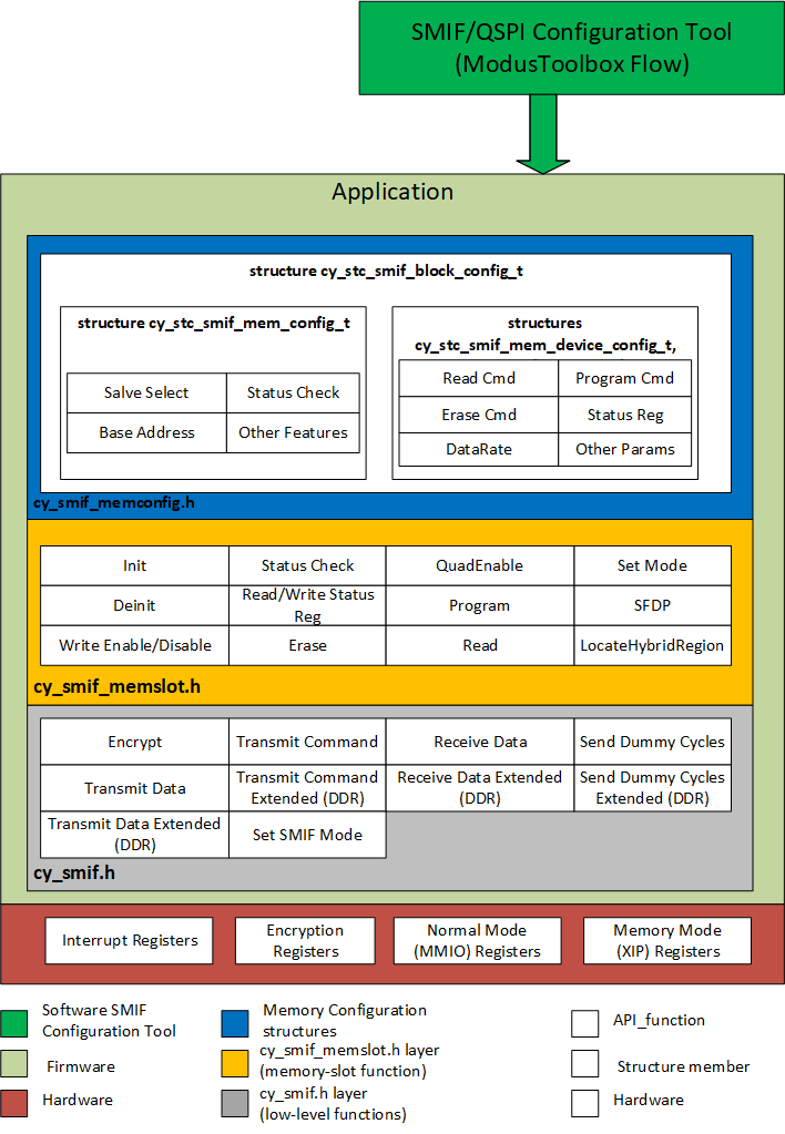
The functions and other declarations used in this driver are in cy_smif.h and cy_smif_memslot.h (if used). If you are using the ModusToolbox QSPI Configurator, also include cycfg_qspi_memslot.h.
SMIF: Serial Memory Interface: This IP block implements an SPI-based communication interface for interfacing external memory devices to the MCU. The SMIF supports SPI, dual SPI (DSPI), quad SPI (QSPI), dual QSPI and octal SPI.
Features
- Standard SPI Master interface
- Supports single/dual/quad/octal SPI memory devices
- Supports dual quad SPI mode
- Design-time configurable support for multiple (up to 4) external serial memory devices
- eXecute-In-Place (XIP) operation mode for both read and write accesses with 4KB XIP read cache and on-the-fly encryption and decryption
- Supports external serial memory initialization via Serial Flash Discoverable Parameters (SFDP) standard
The primary usage model for the SMIF is that of an external memory interface. The SMIF is capable of interfacing with different types of memory, up to four types.
SMIF driver is divided into three layers
- cy_smif.h API
- cy_smif_memslot.h API
- SMIF configuration structures
The SMIF API is divided into the low-level functions and memory-slot functions. Use the low level API for the SMIF block initialization and for implementing a generic SPI communication interface using the SMIF block.
The memory slot API has functions to implement the basic memory operations such as program, read, erase etc. These functions are implemented using the memory parameters in the memory device configuration data structure. The Cy_SMIF_MemInit() API initializes all the memory slots based on the settings in the array.
- Note
- Above image is applicable only for SMIF v3 IP.
- Note
- Above image is applicable only for SMIF v1 IP.
The QSPI Configurator tool is a stand-alone application that is a part of ModusToolbox. It can be accessed within ModusToolbox via the Peripheral -> Serial Memory Interface -> External Tools -> Launch QSPI Configurator button, or from the <CY_TOOLS_PATHS>/qspi-configurator directory.
The tool generates *.c and *.h file with configuration structures. These configuration structures are input parameters for cy_smif_memslot API level.
- Warning
- The driver is not responsible for external memory persistence. You cannot edit a buffer during the Read/Write operations. If there is a memory error, the SMIF ip block can require a reset. To determine if this has happened, check the SMIF busy status using Cy_SMIF_BusyCheck() and implement a timeout. Reset the SMIF block by toggling CTL.ENABLED. Then reconfigure the SMIF block.
For the Write operation, check that the SMIF driver has completed transferring by calling Cy_SMIF_BusyCheck(). Also, check that the memory is available with Cy_SMIF_MemIsBusy() before proceeding.
Simple example of external flash memory programming using low level SMIF API. All steps mentioned in example below are incorporated in Cy_SMIF_MemCmdWriteEnable(), Cy_SMIF_MemCmdProgram(), and Cy_SMIF_MemIsBusy() of the memory slot level API.
- Warning
- Example is simplified, without checks of error conditions.
- Note
- Flash memories need erase operation before programming. Refer to external memory datasheet for specific memory commands.
0x06U,
CMD_WITHOUT_PARAM,
CMD_WITHOUT_PARAM,
1U,
&smifContext);
uint8_t tst_txBuffer[TX_SIZE];
0x02U,
address,
MEMORY_ADDRESS_SIZE,
0U,
&smifContext);
NULL,
&smifContext);
bool memBusy;
do
{
uint8_t readReg = 0U;
0x05U,
CMD_WITHOUT_PARAM,
CMD_WITHOUT_PARAM,
0U,
&smifContext);
1U,
NULL,
&smifContext);
memBusy = ((readReg & MEM_WIP_MASK) != 0U);
}
while(memBusy);
@ CY_SMIF_WIDTH_SINGLE
Single SPI mode.
Definition: cy_smif.h:513
@ CY_SMIF_SLAVE_SELECT_0
The SMIF slave select 0
Definition: cy_smif.h:731
cy_en_smif_status_t Cy_SMIF_ReceiveData(SMIF_Type *base, uint8_t *rxBuffer, uint32_t size, cy_en_smif_txfr_width_t transferWidth, cy_smif_event_cb_t RxCompleteCb, cy_stc_smif_context_t *context)
This function implements the receive data phase in the memory command.
Definition: cy_smif.c:762
__STATIC_INLINE bool Cy_SMIF_BusyCheck(SMIF_Type const *base)
This function provides the status of the IP block (False - not busy, True - busy).
Definition: cy_smif.h:1540
cy_en_smif_status_t Cy_SMIF_TransmitCommand(SMIF_Type *base, uint8_t cmd, cy_en_smif_txfr_width_t cmdTxfrWidth, uint8_t const cmdParam[], uint32_t paramSize, cy_en_smif_txfr_width_t paramTxfrWidth, cy_en_smif_slave_select_t slaveSelect, uint32_t completeTxfr, cy_stc_smif_context_t const *context)
This function transmits a command byte followed by a parameter which is typically an address field.
Definition: cy_smif.c:550
cy_en_smif_status_t Cy_SMIF_TransmitData(SMIF_Type *base, uint8_t const *txBuffer, uint32_t size, cy_en_smif_txfr_width_t transferWidth, cy_smif_event_cb_t TxCompleteCb, cy_stc_smif_context_t *context)
This function is used to transmit data using the SMIF interface.
Definition: cy_smif.c:628
For the Read operation, before accessing the read buffer, check that it is ready by calling Cy_SMIF_GetTxFifoStatus().
Simple example of external flash memory read using low level SMIF API. All steps mentioned in example below are incorporated in Cy_SMIF_MemCmdRead() of the memory slot level API.
- Warning
- Example is simplified, without checks of error conditions.
- Note
- Refer to external memory datasheet for specific memory commands.
uint8_t address[MEMORY_ADDRESS_SIZE] = {0U,0U,0U};
uint8_t tst_rxBuffer[RX_SIZE];
0x03U,
address,
MEMORY_ADDRESS_SIZE,
0U,
&smifContext);
NULL,
&smifContext);
@ CY_SMIF_RX_BUSY
The data reception is in progress.
Definition: cy_smif.h:676
cy_en_smif_txfr_status_t Cy_SMIF_GetTransferStatus(SMIF_Type const *base, cy_stc_smif_context_t const *context)
This function provides the status of the transfer.
Definition: cy_smif.c:897
The user should invalidate the cache by calling Cy_SMIF_CacheInvalidate() when switching from the MMIO mode to XIP mode.
Configuration Considerations
PDL API has common parameters: base, context, config described in PDL Design section.
See the documentation for Cy_SMIF_Init() and Cy_SMIF_MemInit() for details on the required configuration structures and other initialization topics.
The normal (MMIO) mode is used for implementing a generic SPI/DSPI/QSPI/dual QSPI/octal SPI communication interface using the SMIF block. This interface can be used to implement special commands like Program/Erase of flash, memory device configuration, sleep mode entry for memory devices or other special commands specific to the memory device. The transfer width (SPI/DSPI/QSPI/octal SPI) of a transmission is a parameter set for each transmit/receive operation. So these can be changed at run time.
In a typical memory interface with flash memory, the SMIF is used in the memory mode when reading from the memory and it switches to the normal mode when writing to flash memory. A typical memory device has multiple types of commands.
The SMIF interface can be used to transmit different types of commands. Each command has different phases: command, dummy cycles, and transmit and receive data which require separate APIs.
SMIF Initialization
Create interrupt function and allocate memory for SMIF context structure
void SMIF_Interrupt_User(void)
{
}
The SMIF internal context data.
Definition: cy_smif.h:997
__STATIC_INLINE void Cy_SMIF_Interrupt(SMIF_Type *base, cy_stc_smif_context_t *context)
The Interrupt Service Routine for the SMIF.
Definition: cy_smif.h:1575
SMIF driver initialization for low level API usage (cysmif.h)
#define NUMBER_OF_EXTERNAL_MEM (2U)
#define SMIF_PRIORITY (1U)
#define SMIF_TIMEOUT_1_MS (1000U)
#if defined (CY_DEVICE_CAT1A)
#define SMIF_INTERRUPT smif_interrupt_IRQn
#elif defined (CY_DEVICE_CAT1B)
#define SMIF_INTERRUPT smif_interrupt_normal_IRQn
#elif defined (CY_DEVICE_CAT1C)
#if (defined(SMIF_SMIF_NR) && SMIF_SMIF_NR != 1)
#define SMIF_INTERRUPT smif_0_smif0_interrupt_IRQn
#else
#define SMIF_INTERRUPT smif_0_interrupt_IRQn
#endif
#elif (CY_IP_MXSMIF_VERSION == 6u)
#define SMIF_INTERRUPT smif_0_smif0_interrupt_nsec_IRQn
#endif
{
#if (CY_CPU_CORTEX_M0P)
NvicMux7_IRQn,
SMIF_INTERRUPT,
#elif (defined(CPUSS_SYSTEM_IRQ_PRESENT) && CPUSS_SYSTEM_IRQ_PRESENT == 1)
#else
SMIF_INTERRUPT,
#endif
SMIF_PRIORITY
};
__enable_irq();
#if ((__CORTEX_M == 0) || (defined(CPUSS_SYSTEM_IRQ_PRESENT) && CPUSS_SYSTEM_IRQ_PRESENT == 1))
NVIC_EnableIRQ(NvicMux7_IRQn);
#else
NVIC_EnableIRQ(SMIF_INTERRUPT);
#endif
{
.deselectDelay = DESELECT_DELAY,
};
Cy_SMIF_Init(SMIF, &tst_smifConfig, SMIF_TIMEOUT_1_MS, &smifContext);
uint32_t mode
Specifies the mode of operation cy_en_smif_mode_t.
Definition: cy_smif.h:964
The SMIF configuration structure.
Definition: cy_smif.h:963
@ CY_SMIF_NORMAL
Command mode (MMIO mode).
Definition: cy_smif.h:573
@ CY_SMIF_SEL_INVERTED_INTERNAL_CLK
The SMIF internal inverted clock.
Definition: cy_smif.h:753
@ CY_SMIF_BUS_ERROR
Generates a bus error.
Definition: cy_smif.h:524
void Cy_SMIF_Enable(SMIF_Type *base, cy_stc_smif_context_t *context)
Enables the operation of the SMIF block.
Definition: cy_smif.c:921
cy_en_smif_status_t Cy_SMIF_Init(SMIF_Type *base, cy_stc_smif_config_t const *config, uint32_t timeout, cy_stc_smif_context_t *context)
This function initializes the SMIF block as a communication block.
Definition: cy_smif.c:75
Initialization configuration structure for a single interrupt channel.
Definition: cy_sysint.h:227
cy_en_sysint_status_t Cy_SysInt_Init(const cy_stc_sysint_t *config, cy_israddress userIsr)
Initializes the referenced interrupt by setting the priority and the interrupt vector.
Definition: cy_sysint_v2.c:80
#define CY_SYSINT_INTRSRC_MUXIRQ_SHIFT
Bit 0-11 indicate system interrupt and bit 12-15 will indicate the CPU IRQ.
Definition: cy_sysint.h:179
Additional steps to initialize SMIF driver for memory slot level API usage (cy_smif_memslot.h).
{
.baseAddress = 0x18000000UL,
.memMappedSize = 0xFFE00000UL,
.dualQuadSlots = 0x0UL,
.deviceCfg = &S25FL512S,
#if(CY_IP_MXSMIF_VERSION>=2)
.mergeTimeout = CY_SMIF_MERGE_TIMEOUT_256_CYCLES
#endif
};
{
.baseAddress = 0x0UL,
.memMappedSize = 0x0UL,
.dualQuadSlots = 0x0UL,
.deviceCfg = &autodetectedMemory,
#if(CY_IP_MXSMIF_VERSION>=2)
.mergeTimeout = CY_SMIF_MERGE_TIMEOUT_256_CYCLES
#endif
};
&memSs0,
&memSs1,
};
cy_en_smif_slave_select_t slaveSelect
Determines the slave select where the memory device is placed.
Definition: cy_smif_memslot.h:768
This SMIF memory configuration structure is used to store the memory configuration for the memory mod...
Definition: cy_smif_memslot.h:766
This configuration structure of the SMIF memory device is used to store device-specific parameters.
Definition: cy_smif_memslot.h:718
@ CY_SMIF_DATA_SEL0
smif.spi_data[0] = DATA0, smif.spi_data[1] = DATA1, ..., smif.spi_data[7] = DATA7.
Definition: cy_smif.h:552
@ CY_SMIF_DATA_SEL2
smif.spi_data[4] = DATA0, smif.spi_data[5] = DATA1, ..., smif.spi_data[7] = DATA3.
Definition: cy_smif.h:562
@ CY_SMIF_SLAVE_SELECT_1
The SMIF slave select 1
Definition: cy_smif.h:732
#define CY_SMIF_FLAG_DETECT_SFDP
Enables the Autodetect using the SFDP.
Definition: cy_smif_memslot.h:92
#define CY_SMIF_FLAG_MEMORY_MAPPED
Determines if the device is memory-mapped.
Definition: cy_smif_memslot.h:91
#define CY_SMIF_FLAG_WRITE_ENABLE
Enables the write capability for the memory slave in the memory-mapped mode.
Definition: cy_smif_memslot.h:88
cy_en_smif_status_t Cy_SMIF_MemInit(SMIF_Type *base, cy_stc_smif_block_config_t const *blockConfig, cy_stc_smif_context_t *context)
This function initializes the slots of the memory device in the SMIF configuration.
Definition: cy_smif_memslot.c:101
- Note
- Example does not include initialization of all needed configuration structures (cy_stc_smif_mem_device_cfg_t, cy_stc_smif_mem_cmd_t). SMIF/QSPI Configuration tool generates all configuration structures needed for memslot level API usage.
SMIF XIP Initialization
The eXecute In Place (XIP) is a mode of operation where read or write commands to the memory device are directed through the SMIF without any use of API function calls. In this mode the SMIF block maps the AHB bus-accesses to external memory device addresses to make it behave similar to internal memory. This allows the CPU to execute code directly from external memory. This mode is not limited to code and is suitable also for data read and write accesses. The memory regions available for XIP addresses allocation are defined in a linker script file (.ld).
With SMIF V3 IP (and above), MMIO mode transactions are also allowed when the device is set to XIP mode. However, only blocking SMIF API's are expected to be used for erase or program operations as external flash will be busy for such operation and may not be available for XIP at that moment. User can make use of Cy_SMIF_MemRead, Cy_SMIF_MemWrite, Cy_SMIF_MemEraseSector API's which ensure that user gets control only after completing the requested operation. This will ensure the transaction is complete and then switch back to XIP. In case user wishes to make use of low level API's like Cy_SMIF_TransmitCommand_Ext, Cy_SMIF_TransmitData_Ext, Cy_SMIF_SendDummyCycles_Ext user has to ensure the code is not running already from XIP location and complete the operation before switching back to XIP mode of execution. Also, user has to bound his complete SMIF operation using Cy_SysLib_EnterCriticalSection and Cy_SysLib_ExitCriticalSection so that there is no interruption for the operation due to any other interrupts.
Cy_SMIF_Init(SMIF, &tst_smifConfig, SMIF_TIMEOUT_1_MS, &smifContext);
@ CY_SMIF_MEMORY
XIP (eXecute In Place) mode.
Definition: cy_smif.h:574
void Cy_SMIF_SetDataSelect(SMIF_Type *base, cy_en_smif_slave_select_t slaveSelect, cy_en_smif_data_select_t dataSelect)
This function configures the data select option for a specific slave.
Definition: cy_smif.c:420
void Cy_SMIF_SetMode(SMIF_Type *base, cy_en_smif_mode_t mode)
Sets the mode of operation for the SMIF.
Definition: cy_smif.c:354
- Note
- Example of input parameters initialization is in SMIF Initialization section.
- Warning
- Functions that called from external memory should be declared with long call attribute.
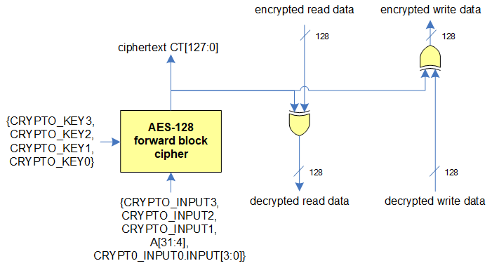
SMIF XIP On-the-fly encryption
In XIP mode, a cryptography component supports on-the-fly encryption for write data and on-the-fly decryption for read data. On-the-fly encryption/decryption in XIP mode can be enabled by setting the flags CY_SMIF_FLAG_CRYPTO_ENABLE. Encryption and decryption are based on the AES-128 forward block cipher: advanced encryption standard blockcipher with a 128-bit key. KEY[127:0] is a secret (private) key programmed into the CRYPTO_KEY3,...,CRYPTO_KEY0 registers using Cy_SMIF_SetCryptoKey. These registers are software write-only. A software read returns 0. In the SMIF hardware, by applying AES-128 with KEY[127:0] on a plaintext PT[127:0], we get a ciphertext CT[127:0]. In XIP mode, the XIP address is used as the plaintext PT[]. The resulting ciphertext CT[] is used on-the-fly and not software accessible. The XIP address is extended with the CRYPTO_INPUT3, ..., CRYPTO_INPUT0 registers. Cy_SMIF_SetCryptoIV can be used to set initialization vector (96-bits). In XIP mode, the resulting ciphertext CT[] (of the encrypted address) is XORed with the memory transfers read data or write data. Note that the AES-128 block cipher is on the address of the data and not on the data itself.
Rules for SMIF Block Usage
- All operations must use one or more dummy cycles between the Command and Address phase (when the MCU drives the data pins) and the device's Response phase (when the device drives the same data pins). Bus contention may occur if no (zero) dummy cycles are used.
- Any transfer that does not allow dummy cycles (such as Register Status Reads) must use the single-bit transfer mode. In single-bit mode, the MCU drives the Command on the Data0 line and the device responds on the Data1 line, so bus contention cannot occur.
More Information
More information regarding the Serial Memory Interface can be found in the component datasheet and the Technical Reference Manual (TRM).
More information regarding the QSPI Configurator tool are in QSPI Configurator user guide.