 |
PSoC 6 Peripheral Driver Library
|
|
PSoC 6 Peripheral Driver Library
|
PDL depends on the Core Library. Download it from https://github.com/cypresssemiconductorco/core-lib and add cy_utils.h to the include search path.
Include cy_pdl.h in your source code to use the library.
To successfully develop software for the PSoC 6 family of devices, you must configure the peripherals to implement desired behavior. In addition, you must configure clocks, GPIO, and interrupts, as well as route signals from one peripheral to another.
This introduction covers some high level concepts that help you understand and use the PDL to accomplish these tasks. The topics are:
This PDL API Reference covers the peripheral drivers. Documentation on other parts of the overall software development kit are in there respective references, such as the Bootloader SDK API Reference and the BLE API Reference.
PDL is the software development kit for the PSoC 6 family of devices. Although called the Peripheral Driver Library it contains much more than driver source code.
The PDL occupies the space between application code and the hardware IP blocks (peripherals). It provides driver source code you use to customize drivers for an application. To see the exact list of available drivers, expand the PDL API Reference in the left menu. It also includes all required device-specific header and startup files.
The PDL manages all register access. This reduces the need to understand register usage and bit fields, thus easing software development for the extensive set of peripherals provided for PSoC 6 devices.
PSoC 6 devices use a dual core architecture with both a Cortex® M4 and a Cortex M0+ device. The hardware defines a shared register set and memory map for all peripherals. This means that, with few exceptions, either core can use any peripheral driver. For example, there is a single RTC driver used by either core, not separate CM4 and CM0+ RTC drivers.
The set of available peripherals varies per device. In some cases there are multiple instances of the same peripheral; for example, multiple Serial Communication Blocks (SCB). Each peripheral instance may itself operate on multiple instances of user data.
To enable a peripheral to be used by either or both cores, as well as multiple instances of configurable peripherals operating on (potentially) multiple instances of data, the PDL implements a simple, consistent design based on three fundamental concepts.
Base Hardware Address: At the hardware level, peripheral features and behavior are controlled by registers. Each peripheral instance has a base hardware address that points to the registers for that instance. The PDL uses this base address to access the necessary registers. A device-specific header file defines the symbols for the base hardware address of each instance of each peripheral. For example, the PSoC 6 BLE Pioneer Kit uses the CY8C6347BZI-BLD53 device. The PDL includes the device-specific header file in the devices folder: <PDL directory>/devices/include/cy8c6347bzi_bld53.h
Each such file defines a symbol that represents a pointer to the base hardware address for each instance of each peripheral on the device. Use this symbol in your code. The next snippet shows the symbols for instances of the SCB peripheral on this device, which supports nine SCB instances:
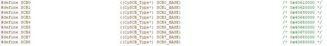
The header file contains similar definitions for each peripheral.
Configuration Structure: Each peripheral instance is configurable. Modify values in a PDL configuration structure to change behavior to fit design requirements. The PDL then manages register access using the base hardware address.
Context Structure: A PDL driver may require memory to peform operations. A driver does not allocate memory for this purpose. Firmware allocates the required memory by declaring an instance of a context structure. The address of this variable is passed in function calls. The PDL defines all necessary context structures.
The PDL manages the contents of the context variable. Firmware does not read or write the values of the fields in a context variable. In effect, firmware provides a scratch pad in memory for the PDL driver to do its work. Firmware must ensure that a context variable remains in scope when in use. Typically a context variable is declared as static, or as a global variable.
Many PDL API function calls require a parameter representing one or more of these three concepts. The precise details vary per peripheral, but the design is consistent. There are three commonly-named parameters in the PDL, used to support this design.
| Parameter | Data Type | Purpose |
|---|---|---|
base | <peripheral>_Type* | Base hardware address for an instance of a peripheral |
config | cy_stc_<peripheral>_config_t* | A structure with configuration information for a peripheral |
context | cy_stc_<peripheral>_context_t* | A structure declared by firmware to allocate memory for a peripheral |
In addition, all functions follow this naming convention: Cy_<Peripheral>_<FunctionName>().
Firmware must initialize and enable a driver before using it. The PDL API has functions for the purpose. Some peripherals may not implement one or more of these common functions because they aren’t needed for that particular peripheral.
| Name | Purpose | Example |
|---|---|---|
| Cy_<Peripheral>_Init() | Initialize a peripheral, typically based on a config structure | Cy_SCB_UART_Init() |
| Cy_<Peripheral>_DeInit() | de-initialize a peripheral | Cy_SCB_UART_DeInit() |
| Cy_<Peripheral>_Enable() | turn on the peripheral | Cy_SCB_UART_Enable() |
| Cy_<Peripheral>_Disable() | turn off the peripheral | Cy_SCB_UART_Disable() |
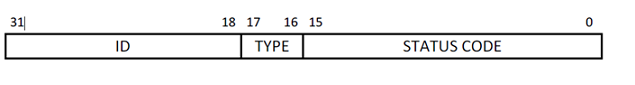
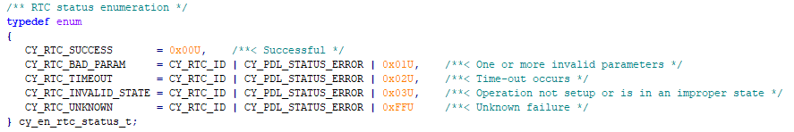
Return Status Code: Each driver has a unique return status enumeration type - cy_en_<peripheral>_status_t. The type is used by functions within the driver to indicate the return status. Drivers return success status code with a value of 0. The status code consists of the following fields:
Example of return status type:
A direct effect of the context structure described in the PDL Design section is that the PDL drivers do not dynamically allocate memory. The user allocates the memory required by the driver, by declaring a context structure.
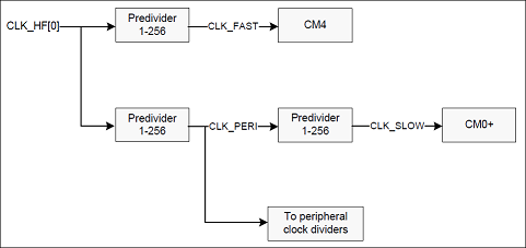
PSoC 6 devices have several source clocks, a Frequency Lock Loop (FLL), and one or more phase lock loops (PLL). Firmware configures and enables the source clocks and clock dividers based on design requirements. The clocks and clock tree are fully documented in the Clocking System chapter of the Technical Reference Manual (TRM).
A peripheral can only be clocked by a peripheral clock divider. For example, the PSoC 6 BLE has 29 peripheral clock dividers. CLK_PERI is the source clock for all programmable peripheral clock dividers. The output of any divider can be routed to any peripheral.
The ModusToolbox Device Configurator provides a friendly user interface for managing clocks on the System and Peripheral-Clocks tabs. The Device Configurator generates the required code based upon your design (../GeneratedSources/cycfg_system.c/.h and cycfg_clocks.c/.h files correspondently).
If you create your design without the Device Configurator you must manage the clock configuration via code you write. The PDL provides the System Clock (SysClk) driver for this purpose.
The PSoC 6 I/O system provides the interface between the CPU core and peripheral components to the outside world. With a PSoC 6 device firmware can route most signals to most pins, which greatly simplifies circuit design and board layout.
The GPIO pins in PSoC 6 are grouped into ports; a port has a maximum of eight GPIOs. The high-speed I/O matrix (HSIOM) is a set of high-speed multiplexers that route internal CPU and peripheral signals to and from GPIOs. HSIOM allows GPIOs to be shared with multiple functions and multiplexes the pin connection to a particular peripheral selected by the user. See the I/O System chapter of the TRM for full technical details.
Each pin has several characteristics, such as drive mode, slew rate, and buffer mode. You can configure pins at the Pins tab of the ModusToolbox Device Configurator tool.
Firmware can configure and modify a pin at run time as well. The PDL provides the General Purpose Input Output (GPIO) driver to assist. Firmware can initialize, read, write, set, clear, or invert the state of a pin, get or clear the interrupt state on the pin, and more.
A PSoC 6 device supports many system and peripheral interrupts. These are processed by the Nested Vector Interrupt Controller (NVIC) of the individual core. On the Cortex M4, system interrupt source 'n' is directly connected to the corresponding IRQn. The Cortex-M0+ has fewer IRQns than there are interrupt sources. Firmware can connect any interrupt source to any IRQn on the Cortex M0+. However, some CM0+ IRQs are reserved for system use. See the System Interrupt (SysInt) driver documentation. The NVIC takes care of enabling/disabling individual interrupt IRQs, priority resolution, and communication with the CPU core. See the Interrupts chapter of the TRM.
Interrupts are set up at the system level for any peripheral that handles an interrupt. The PDL provides the System Interrupt (SysInt) driver to assist in configuring interrupts. To connect an interrupt service routine (ISR) to an interrupt signal, initialize the system interrupt with a configuration structure (containing the interrupt number and priority), and provide the address of the ISR. For the M0+ device, also provide the interrupt source (because of interrupt muxing). Various drivers have support for setting, clearing, and masking interrupts, or to specify a callback routine.
The System Power Management driver (SysPM) implements a callback mechanism to handle power mode transitions. This mechanism allows any driver to perform any operation required to prepare for the specific power mode, or to abort the transition. Power mode transition callbacks are maintained as a linked list. The driver calls them in order, either first to last, or last to first, as appropriate.
Every driver concerned with entering or returning from a low-power state must register callback functions with SysPM. If there is any order dependence among the drivers in your firmware, register the callbacks in the order you require. For example, callbacks that configure global resources, such as clock frequencies, should be registered last.
If your firmware does not register any SysPM callbacks, the device just executes the power mode transition.
See the System Power Management (SysPM) documentation for details.
A design may require that the output from one peripheral triggers behavior in another peripheral. For example, a SPI (SCB) peripheral block receives data. After the data is received, a signal from the SCB triggers a DMA channel to transfer the received data to a memory buffer.
The PSoC 6 trigger multiplexer block implements a collection of multiplexers that can connect any trigger signal from any peripheral to any other peripheral. To support this the hardware implements an input layer and an output layer. The input layer has reduction multiplexer groups, which have as input the trigger signals coming from different peripheral blocks. The reduction multiplexer routes these signals to an intermediate trigger signal. The output side uses that intermediate trigger as its input, and uses a distribution multiplexer to send that signal to one or more peripherals. The design also supports a software trigger for any signal. See the Trigger Multiplexer Block chapter of the TRM.
The PDL provides the Trigger Multiplexer (TrigMux) driver to enable this. To route a trigger signal from one peripheral in the PSoC to another, firmware configures both a reduction multiplexer and a distribution multiplexer, to define where the signal comes from, and where it goes to. The software trigger triggers all peripherals connected to that output signal.
In a dual-core system, care must be taken to ensure that the two cores don’t access the same resource simultaneously. The IPC hardware block provides the functionality for multiple processors to communicate and synchronize their activities. See the Inter-Processor Communication chapter of the TRM.
The PDL provides the Inter-Process Communication (IPC) driver to enable this.
The API implements the concept of a Pipe. A Pipe is typically a full-duplex communication channel between CPU cores. A pipe allows a single conduit to transfer messages or data to and from multiple processes or CPUs.
A pipe has two endpoints, one on each core. Each endpoint contains a dedicated IPC channel and an interrupt. The interrupt handles both notify and release events for the endpoint. Each endpoint has clients. A client is a process that receives a message and operates on the data in that message. A pipe can service an arbitrary number of clients on either endpoint. This design enables any number of processes on the sending core to put arbitrary data into a single pipe, destined for one or more recipients.
The data in the pipe is limited to a 32-bit value, which is a pointer to data of arbitrary complexity.
The IPC driver also implements a semaphore mechanism, so firmware can control access to shared resources.
The PDL was designed to support multithreaded operations. Most of the PDL API functions are reentrant by satisfying the following conditions:
Some drivers are not thread-safe because they contain internal static state of the driver/peripheral. You can arrange your application code or use your own locking mechanism to ensure that functions in these drivers are called by only one thread at a time. Call initialization functions once to initialize the peripheral before creating any additional thread that will use the peripheral.
The System Library files define an assert mechanism that is used extensively by the PDL for parameter checking. It is enabled by default. It is recommended that asserts remain enabled when debugging firmware.
Firmware can use the same assert mechanism. The default assertion handler Cy_SysLib_AssertFailed() is weakly linked. Firmware can override that function to implement custom assert handling.