 |
PSoC 6 Peripheral Driver Library
|
|
PSoC 6 Peripheral Driver Library
|
The inter-processor communication (IPC) driver provides a safe and reliable method to transfer data between CPUs.
Hardware locking ensures that only one device can acquire and transfer data at a time so no data is lost or overwritten by asynchronous processes or CPUs.
Include either cy_ipc_pipe.h or cy_ipc_sema.h. Alternatively include cy_pdl.h to get access to all functions and declarations in the PDL.
There are three parts to the API:
Firmware does not need to use the DRV API. It can implement IPC functionality entirely with the PIPE and SEMA APIs.
IPC is implemented in hardware as a collection of individual communication channels, each with a set of 32-bit registers. The IPC design implements a set of interrupts that enable each processor to notify the other that data is available, or has been processed. There is also a locking mechanism that allows only one CPU to gain access at a time.
The Driver-level API manages each channel's registers to implement IPC functionality. For information on the IPC registers, see the IPC chapter of the Technical Reference Manual (TRM).
At the hardware level, communication is a five-step process.
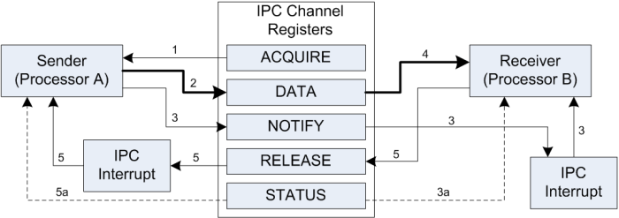
These transactions are handled transparently by the DRV-level API. Use the PIPE and SEMA layers of the API to implement communication in your application. The data transferred is limited to a single 32-bit value. As implemented by the PIPE API, that value is a pointer to a data structure of arbitrary size and complexity.
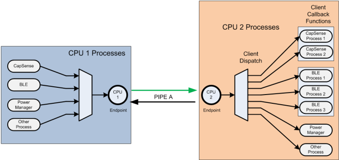
The Pipe is the key element in the PDL design. A pipe is typically a full-duplex communication channel between CPU cores. A pipe allows a single conduit to transfer messages or data to and from multiple processes or CPUs.
A pipe has two endpoints, one on each core. Each endpoint contains a dedicated IPC channel and an interrupt. IPC channels 0-7(8 for the CYB064XX devices) and IPC interrupts 0-7 are reserved for system use.
The pipe also contains the number of clients it supports, and for each client a callback function. So the pipe can service a number of clients, each with a separate callback function, on either endpoint. The number of clients a pipe supports is the sum of each endpoint's clients.
This design enables any number of processes on the sending core to put arbitrary data into a single pipe. The first element of that data is the client ID of the client that should handle the data.
An interrupt notifies the receiving core that data is available. The receiving core parses the data to identify the client, and then dispatches the event to the appropriate client via the client callback function. An interrupt notifies the sending core that the receiver is finished. In this way a single pipe can manage arbitrary data transfers between cores with data flowing in either direction.
The application can use semaphores to control access to shared resources, as required by the application's logic.
The PDL provides specific files that set up default IPC functionality. They are system_psoc6.h, system_psoc6_cm0plus.c and system_psoc6_cm4.c. You can modify these files based on the requirements of your design. If you use PSoC Creator as a development environment, it will not overwrite your changes when you generate the application or build your code.
A pipe is a communication channel between two endpoints. PSoC 6 devices support 16 IPC channels, and 16 IPC interrupts, each numbered 0-15. Following IPC Channels and IPC interrupts are reserved for system use:
| IPC Resource | PSoC 61 / PSoC 62 / PSoC 63 | PSoC 64 |
|---|---|---|
| IPC channels (16 available) | 8 reserved (0-7) | 13 reserved (0-12) |
| IPC interrupts (16 available) | 8 reserved (0-7) | 13 reserved (0-12) |
A full duplex pipe uses two IPC channels, one per endpoint. Each endpoint specifies all the information required to process a message (either sent or received). Each endpoint is configured to use an IPC channel, and an IPC interrupt. Common practice is to use the interrupt with the same number as the IPC channel. However, IPC Interrupts are not directly associated with the IPC channels, so any channel can use any interrupt. Any IPC channel can trigger 0, 1 or all the IPC interrupts at once, depending on the Notify or Release masks used.
It is also possible to set up a one-directional pipe, using a single IPC channel. In this design one processor is always the sender, and the other is always the receiver. However, there are still two endpoints.
A pipe supports an arbitrary number of clients with an array of callback functions, one per client. The client ID is the index number into the array for the client. After a pipe is configured and initialized, the application calls Cy_IPC_Pipe_RegisterCallback() once per client to register each client's callback function. Multiple clients can use the same callback function. The endpoints in a pipe share the callback array.
Use Cy_IPC_Pipe_SendMessage() to send data. You specify both the "to" and "from" endpoints, and a callback function to be used when the data transfer is complete. The data is a 32-bit void pointer. The data pointed to is arbitrary, and can be an array, a structure, or a location in memory. The only limitation is that the first element of the data must be a 32-bit unsigned word containing a client ID number. The ID number is the index into the callback array.
When a message is sent, the receiving endpoint's interrupt handler is called. The ISR can perform any task required by the design. However, as part of its function it calls Cy_IPC_Pipe_ExecCallback. This function retrieves the client ID from the data and calls the associated callback function. The user-supplied callback function handles the data in whatever way is appropriate based on the application logic.
After the callback function is returned by the receiver, it invokes the release callback function defined by the sender of the message.
A semaphore is a flag the application uses to control access to a shared resource. The SEMA-level API uses an IPC channel to implement semaphores. Startup code sets up a default semaphore system. The default system creates an array of 128 semaphores (four 32-bit values). Semaphores 0-15 are reserved for system use. See Configuration Considerations - SEMA.
Functions are available to initialize the semaphore system, to set or clear a semaphore, or to get the semaphore's current status. Application logic uses SEMA functions to relate a particular semaphore to a particular shared resource, and set, clear, or check the flag when accessing the shared resource.
There are none. The startup files set up the required CYPIPE for system use. Do not modify the CYPIPE. It uses IPC channels 5 and 6 to implement full duplex communication between cores. See System Interrupt (SysInt) for background.
To create your own pipe (USRPIPE) you should edit startup files and take 4 steps:
Startup code calls Cy_IPC_Sema_Init() with default values to set up semaphore functionality. By default the semaphore system uses IPC channel 4, and creates 128 semaphores. Do not change the IPC channel. You can change the number of semaphores.
To change the number of semaphores, modify this line of code in system_psoc6.h.
Startup also declares array ipcSemaArray to hold the semaphore flags based on the size defined for this symbol. Use increments of 32. You must have at least 32 semaphores. Semaphores 0-15 are reserved for system use. Your application can use semaphores greater than 15.
If the default startup file is not used, or SystemInit() is not called in your project, call the following three functions prior to executing any flash or EmEEPROM write or erase operation:
See the technical reference manual(TRM) for more information on the IPC.
| MISRA Rule | Rule Class (Required/Advisory) | Rule Description | Description of Deviation(s) |
|---|---|---|---|
| 10.3 | R | The value of a complex expression of integer type shall be cast only to a type of the same signedness that is no wider than the underlying type of the expression. | The cast from integer to enumeration value is used to calculate the interrupt vector source from the integer number of the IPC interrupt structure, so there is no way to avoid this cast. |
| 11.4 | A | A cast should not be performed between a pointer to the void to a pointer to the object type. | The cast from the void to pointer and vice versa is used to transmit data via the IPC (Inter Process Communication) channel by exchanging the pointer. We exchange only one pointer, so there is no way to avoid this cast. |
| Version | Changes | Reason for Change |
|---|---|---|
| 1.40.2 | Updated information about IPC resources reserved for the system usage in PIPE layer section. | Documentation enhancement. |
| 1.40.1 | Minor documentation updates. | Documentation enhancement. |
| 1.40 | Moved cy_semaData structure to the RAM section called ".cy_sharedmem". | Support Secure Boot devices. |
| 1.30 | Flattened the organization of the driver source code into the single source directory and the single include directory. | Driver library directory-structure simplification. |
| Moved the Cy_IPC_SystemSemaInit(), Cy_IPC_SystemPipeInit() functions implementation from IPC to Startup, removed cy_ipc_config.c and cy_ipc_config.h files. | Changed IPC driver configuration method from compile time to run time. | |
| Added register access layer. Use register access macros instead of direct register access using dereferenced pointers. | Makes register access device-independent, so that the PDL does not need to be recompiled for each supported part number. | |
| 1.20 | Added Cy_IPC_Pipe_ExecuteCallback function. Updated documentation about user pipe initialization. | Interface improvement, documentation update |
| 1.10.1 | Updated description of the Cy_IPC_Pipe_Init, Cy_IPC_Pipe_EndpointInit, Cy_IPC_Sema_Set functions. Added / updated code snippets. | Documentation update and clarification |
| 1.10 | Added support for more IPC structures | New device support |
| 1.0 | Initial version |
API Reference | |
| IPC driver layer (IPC_DRV) | |
| The functions of this layer are used in the higher IPC levels (Semaphores and Pipes). | |
| IPC semaphores layer (IPC_SEMA) | |
| The semaphores layer functions made use of a single IPC channel to allow multiple semaphores that can be used by system or user function calls. | |
| IPC pipes layer (IPC_PIPE) | |
| The Pipe functions provide a method to transfer one or more words of data between CPUs or tasks. | |