 |
PSoC 6 Peripheral Driver Library
|
|
PSoC 6 Peripheral Driver Library
|
The USBFS driver provides an API to interact with a fixed-function USB block.
The functions and other declarations used in this driver are in cy_usbfs_dev_drv.h. You can include cy_pdl.h to get access to all functions and declarations in the PDL.
The USB block supports Host and Device modes of operation. This version of the driver supports only Device mode.
Features:
The primary usage model for the USBFS driver is to provide a defined API interface to USB Device Middleware component that works on top of it.
The driver also provides an API interface for the application to implement the required functionality:
This section explains how to configure the USBFS driver and system resources to enable USB Device operation. The pointers to the populated cy_stc_usbfs_dev_drv_config_t configuration structure and allocated context are passed in the middleware initialization. function Cy_USB_Dev_Init. After middleware initialization, it calls Cy_USBFS_Dev_Drv_Init to initialize the USBFS driver for Device operation.
To configure the USBFS driver in Device mode, the configuration structure cy_stc_usbfs_dev_drv_config_t parameters must be populated. The configuration structure content significantly depends on the selected endpoints management mode parameter:
CY_USBFS_DEV_DRV_EP_MANAGEMENT_CPU
The epAccess, intrLevelSel and enableLpm must be provided. All other parameters are do not cares for this mode. Refer to section Configure Interrupts to get information about intrLevelSel configuration.
CY_USBFS_DEV_DRV_EP_MANAGEMENT_DMA
To enable DMA operation, the DMA channels must be assigned for each endpoint to be used. Each DMA channel needs a single DMA descriptor to operate. The USBFS driver defines the DMA configuration structure cy_stc_usbfs_dev_drv_dma_config_t to be populated for each DMA channel. The code example below provides an initialized USBFS driver DMA configuration structure:
The pointers to the DMA configuration structure are required into the cy_stc_usbfs_dev_drv_config_t USBFS driver configuration structure to allow the USBFS driver to use DMA channels for used endpoints. The dmaConfig[0] field expects a pointer to the DMA configuration for data endpoint 1, the dmaConfig[1] field pointer to the DMA configuration for data endpoint 2, and so on up to data endpoint 8. The code example below provides an initialized USBFS driver configuration structure which uses endpoint 1:
CY_USBFS_DEV_DRV_EP_MANAGEMENT_DMA_AUTO
DMA Automatic mode needs a DMA channels configuration similar to the described above. But it also requires one more DMA descriptor for each DMA channel and DMA output trigger multiplexer. Refer to the Assign and Route DMA Channels section, for more detail about the trigger multiplexer . The code example below provides an initialized USBFS driver DMA configuration structure:
The driver requires a buffer for data endpoints to operate. This buffer must be allocated by the user. The buffer size is equal to the sum of all used endpoints maximum packet sizes. If an endpoint belongs to more than one alternate setting, select the greatest maximum packet size for this endpoint. The driver configuration structure cy_stc_usbfs_dev_drv_config_t parameters epBuffer and epBufferSize pass the buffer to the driver.
The code example below provides an initialized USBFS driver configuration structure that uses data endpoint 1 with a maximum packet size of 63 bytes and set 16-bit access:
Only dedicated USB pins can be used for USB operation. Keep the default USB pins configuration because after the USBFS driver initializes, the USB block takes control over the pins and drives them properly.
The USB hardware block requires two clock sources for operation:
The code example below shows the connection source path 1 (which expected provide 48 MHz -/+ 0.25% clock) to Clk_HF3 and Bus Reset clock (Clk_Peri assumed to be 50 MHz):
Refer to SysClk (System Clock) driver API for more detail about clock configuration.
The FLL (Clock Path 0) with ECO also can be used as an alternative USB source with the next configuration settings, for 48 MHz:
And for 96 MHz:
Use these structures with Cy_SysClk_FllManualConfigure
The USBFS driver requires a DMA controller to operate in DMA Manual and Automatic modes. The USB hardware block supports the DMA request and feedback lines for each data endpoint. Therefore, up to eight DMA channels serve eight data endpoints. The connection between the USB block and the DMA channels is set using the trigger muxes infrastructure. The USB block output DMA request line is connected to the DMA channel trigger input. This allows the USB block to request a DMA transfer. The DMA completion output is connected to the USB block burst end input. This allows the USB block to get notification that a DMA transfer has been completed and a next DMA request can be sent. The USBFS driver DMA configuration structure requires the outTrigMux field to provide the trigger mux that performs DMA completion and USB block burst end connection.
Refer to TrigMux (Trigger Multiplexer) for more detail on the routing capabilities.
The code examples below shows a connection DMA channel and USB block and the define for outTrigMux field initialization for the CY8C6xx6 or CY8C6xx7 devices.
The interrupts are mandatory for the USBFS driver operation. The USBFS block provides multiple interrupt sources to be assigned to trigger one of the three interrupts: Low, Medium, or High. This allows to assign different priority to the interrupt sources handling. The cy_stc_usbfs_dev_drv_config_t structure provides the intrLevelSel field which initializes the INTR_LVL_SEL register. This register configures which interrupt the interrupt source will trigger.
The recommended/default configuration is:
However, the final configuration must be defined by the application.
The Cy_USBFS_Dev_Drv_Interrupt function must be called in the interrupt handler for the selected USB block instance. Note that the Cy_USBFS_Dev_Drv_Interrupt has the parameter intrCause that must be assigned by calling the appropriate interrupt cause function:
Finally, the interrupts must be configured and interrupt handler routines hook up to NVIC. The code below assigns the interrupt priorities accordingly to interrupt names. The priorities among the USBFS interrupts are as follows: High - the greatest; Medium - the middle; Low - the lowest.
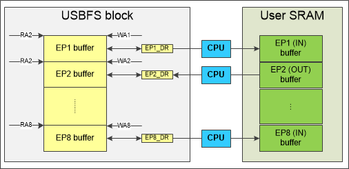
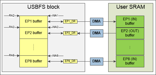
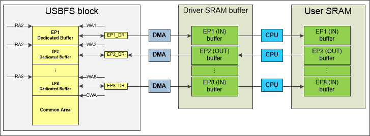
The USBFS hardware block supports three endpoint buffer management modes: CPU (No DMA) mode (Mode 1), Manual DMA mode (Mode 2), and Automatic DMA mode (Mode 3). These modes are listed using enum cy_en_usbfs_dev_drv_ep_management_mode_t. The following sub-sections provide more information about the endpoint buffer management.
The USBFS block has a 512-byte hardware buffer that is divided between all data endpoints used in the selected configuration. How the hardware buffer is divided between endpoints depends on the selected endpoint buffer management modes:
To access the hardware buffer, the endpoint data register is read or written by CPU or DMA. On each read or write, buffer pointers are updated to access a next data element.
The USBFS block provides two sets of data registers: 8-bit and 16-bit. Either the 8-bit endpoint data register or the 16-bit endpoint data register can be used to read/write to the endpoint buffer. The buffer access is controlled by the epAccess field of the driver configuration structure cy_stc_usbfs_dev_drv_config_t. The endpoint hardware buffer and SRAM buffer must be allocated using the rules below when the 16-bit access is used:
The driver provides the CY_USBFS_DEV_DRV_ALLOC_ENDPOINT_BUFFER macro that applies the rules above to allocate the SRAM buffer for an endpoint. This macro should be used by application to hide configuration differences. However, in this case the application must ignore extra bytes in the buffer. Alternately, apply the rules above only for the 16-bits access type configuration.
The driver firmware allocates an endpoint hardware buffer (dividing hardware buffer between utilized endpoints). Therefore, for CPU mode (Mode 1) and Manual DMA mode (Mode 2), an endpoint whose maximum packet size is odd, consumes an extra byte in the hardware buffer when the 16-bit access is used. This is not applicable for Automatic DMA mode (Mode 3) because endpoints dedicated buffer are even and aligned.
In addition, to operate in Automatic DMA mode (Mode 3), the driver needs an internal SRAM buffer for endpoints. The buffer size is a sum of all endpoint buffers. When the 16-bit access is used, each endpoint buffer must be allocated using the rules above. The driver configuration structure cy_stc_usbfs_dev_drv_config_t has epBuffer and epBufferSize fields to pass the allocated buffer to the driver.
For example: the USB Device uses three data endpoints whose max packets are 63 bytes, 63 bytes, and 8 bytes. The endpoints buffer for the driver must be allocated as follows:
CPU handles data transfers between the user-provided SRAM endpoint-buffer and the USB block hardware-buffer when Cy_USBFS_Dev_Drv_ReadOutEndpoint or Cy_USBFS_Dev_Drv_LoadInEndpoint is called.
DMA handles data transfers between the user-provided SRAM endpoint buffer and the USB block hardware buffer. The DMA request is issued by CPU to execute a data transfer when Cy_USBFS_Dev_Drv_ReadOutEndpoint or Cy_USBFS_Dev_Drv_LoadInEndpoint.
DMA handles data transfers between the driver SRAM endpoints buffer and the USB block hardware buffer. The USB block generates DMA requests automatically. When USB transfer starts, the USB block triggers DMA requests to transfer data between the driver endpoint buffer and the hardware buffer until transfer completion. The common area acts as a FIFO to (and keeps data that does not fit into) the endpoint dedicated buffer. For IN endpoints, the dedicated buffer is pre-loaded before enabling USB Host access to the endpoint. This gives time for the DMA to provide remaining data before underflow occurs. The USB block hardware has a feedback connection with the DMA and does not issue new DMA request until it receives notification that the previous DMA transfer completed. When the Cy_USBFS_Dev_Drv_ReadOutEndpoint or Cy_USBFS_Dev_Drv_LoadInEndpoint function is called, the memcpy function is used to copy data from/into the driver endpoints buffer to the user-provided endpoint buffer. The driver provides the Cy_USBFS_Dev_Drv_OverwriteMemcpy function to replace memcpy function by one that has been custom implemented (the DMA can be used for data copy).
The driver provides the following callbacks that can be used by the application:
Also, the driver provides callbacks for a Bus Reset event and Control Endpoint 0 communication events (setup packet, in packet, out packet). But these callbacks are used by middleware and must not be used by the application directly. The middleware provides appropriate hooks for these events.
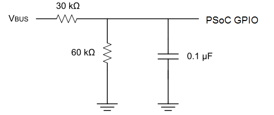
The USB specification requires that no device supplies current on VBUS at its upstream facing port at any time. To meet this requirement, the device must monitors for the presence or absence of VBUS and removes power from the Dp/Dm pull-up resistor if VBUS is absent. The USBFS driver does not provide any support of VBUS monitoring or detection. The application firmware must implement the required functionality using a VDDUSB power pad or GPIO. Refer to the Universal Serial Bus (USB) Device Mode section, sub-section VBUS Detection in the technical reference manual (TRM).
Connect the VBUS through a resistive network when the regular GPIO is used for VBUS detection to save the pin from voltage picks on VBUS, or use GPIO tolerant over the voltage. An example schematic is shown below.
The USBFS driver supports the USB Suspend, Resume, and Remote Wakeup functionality. This functionality is tightly related with the user application. The USBFS driver provides only the API interface which helps the user achieve the desired low-power behavior. The additional processing is required from the user application. The description of application processing is provided below.
Normally, the USB Host sends an SOF packet every 1 ms (at full speed), and this keeps the USB Device awake. The USB Host suspends the USB Device by not sending anything to the USB Device for 3 ms. To recognize this condition, the bus activity must be checked. This can be done using the Cy_USBFS_Dev_Drv_CheckActivity function or by monitoring the SOF interrupt. A suspended device may draw no more than 0.5 mA from VBUS. Therefore, put the device into low-power mode to consume less current. The Cy_USBFS_Dev_Drv_Suspend function must be called before entering low-power mode. When the USB Host wants to wake the device after a suspend, it does so by reversing the polarity of the signal on the data lines for at least 20 ms. The resume signaling is completed with a low-speed end-of-packet signal. The USB block is disabled during Deep Sleep or Hibernate low-power modes. To exit a low-power mode when USB Host drives resume, a falling edge interrupt on Dp must be configured before entering these modes. The Cy_USBFS_Dev_Drv_Resume function must be called after exiting the low-power mode. To resume communication with the USB Host, the data endpoints must be managed: the OUT endpoints must be enabled and IN endpoints must be loaded with data.
If the USB Device supports remote wakeup functionality, the application has to use middleware function Cy_USB_Dev_IsRemoteWakeupEnabled to determine whether remote wakeup was enabled by the USB Host. When the device is suspended and it determines the conditions to initiate a remote wakeup are met, the application must call the Cy_USBFS_Dev_Drv_Force function to force the appropriate J and K states onto the USB bus, signaling a remote wakeup condition. Note that Cy_USBFS_Dev_Drv_Resume must be called first to restore the condition.
Link Power Management is a USB low-power mode feature that provides more flexibility in terms of features than the existing resume mode. This feature is similar to the existing Suspend/Resume, but has transitional latencies of tens of microseconds between power states (instead of 3 to greater than 20 millisecond latencies of the USB 2.0 Suspend/Resume).
USB2.0 Power states are re-arranged as below with the introduction of LPM. The existing power states are re-named with LPM:
LPM state transitions between is shown below:
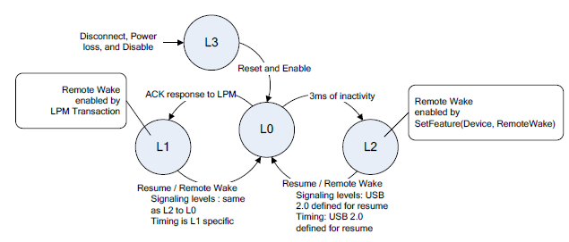
For example, a USB Host must transition a link from L1 (Sleep) to L0 before transitioning it to L2 (Suspend), and similarly when transitioning from L2 to L1.
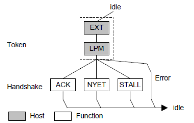
When a USB Host is ready to transition a USB Device from L0 to a deeper power savings state, it issues an LPM transaction to the USB Device. The USB Device function responds with an ACK if it is ready to make the transition or a NYET (Not Yet) if it is not ready (usually because it is has data pending for the USB Host). A USB Device will transmit a STALL handshake if it does not support the requested link state. If the USB Device detects errors in either of the token packets or does not understand the protocol extension transaction, no handshake is returned.
After USB Device is initialized, the LPM transaction is to be acknowledged (ACKed) meaning that the device is ready to enter the requested low-power mode. To override this behavior, use Cy_USBFS_Dev_Drv_Lpm_SetResponse.
The USB block provides an interrupt source to define that an LPM transaction was received and acknowledged (ACKed). Use the Cy_USBFS_Dev_Drv_RegisterLpmCallback function to register the application level callback function to serve the LPM transaction. The callback function can notify the application about an LPM transaction and can use Cy_USBFS_Dev_Drv_Lpm_GetBeslValue read to read Best Effort Service Latency (BESL) values provided as part of an LPM transaction. The BESL value indicates the amount of time from the start of a resume to when the USB Host attempts to begin issuing transactions to the USB Device. The application must use the value BESL to decide which low-power mode is entered to meet wakeup timing. The LPM transaction also contains the field that allows a remote to wake up. Use Cy_USBFS_Dev_Drv_Lpm_RemoteWakeUpAllowed to get its value.
LPM related USB 2.0 Extension Descriptor provides attributes fields named baseline BESL and deep BESL to provide a range of values for different low-power optimization. The recommended use of these fields is that the baseline BESL field will have a value less than the deep BESL field. The expected use is the baseline BESL value communicates a nominal power savings design point and the deep BESL value communicates a significant power saving design point. For example, when the received BESL is less than baseline BESL, leave the device in Active mode. When it is between baseline BESL and deep BESL, put the device into Deep Sleep mode. When it is greater than deep BESL, put the device into Hibernate mode.
For more detail on the USB Full-Speed Device peripheral, refer to the section Universal Serial Bus (USB) Device Mode in the technical reference manual (TRM).
| MISRA Rule | Rule Class (Required/Advisory) | Rule Description | Description of Deviation(s) |
|---|---|---|---|
| 11.4 | A | A cast should not be performed between a pointer to object type and a different pointer to object type. | The function Cy_USBFS_Dev_Drv_LoadInEndpoint and Cy_USBFS_Dev_Drv_ReadOutEndpoint cast buffer parameters from (uint8_t *) to (uint16_t *) when 16-bit access is enabled. To handle alignment issues the macro CY_USBFS_DEV_DRV_ALLOC_ENDPOINT_BUFFER must be used to allocate the buffer for the endpoint. |
| 11.5 | R | A cast shall not be performed that removes any const or volatile qualification from the type addressed by a pointer. |
|
| 14.7 | R | A function shall have a single point of exit at the end of the function. | The functions can return from several points. This is typically done to improve code clarity when returning error status code if input parameters validation fail. |
| 16.7 | A | A pointer parameter in a function prototype should be declared as pointer to const if the pointer is not used to modify the addressed object. | The middleware and USBFS driver define the general function prototypes and pointers to the function types but the function's implementation depends on the configuration. Therefore, some functions' implementations require parameters to be a pointer to const but this is not met because of the generalized implementation approach. |
| Version | Changes | Reason for Change |
|---|---|---|
| 2.20.1 | Minor documentation updates. | Documentation enhancement. |
| 2.20 | Fix configuration register value restoring in resume routine after Deep Sleep. | Fix issue that USB Device stops working in DMA modes after wake up from Deep Sleep. |
| The LPM requests are ignored after wake up from Deep Sleep and the host starts sending SOFs. | Updated Cy_USBFS_Dev_Drv_Resume function to restore LPM control register after exit Deep Sleep. | |
| 2.10 | Returns the data toggle bit into the previous state after detecting that the host is retrying an OUT transaction. | The device was not able to recover the data toggle bit and continues communication through the endpoint after the host retried the OUT transaction (the retried transaction has the same toggle bit as the previous had). |
| 2.0 | The list of changes to support the MBED-OS USB Device stack is provided below:
| Updated the driver to support the MBED-OS USB Device stack and Cypress USB Device middleware. |
| 1.10 | Fixed the Cy_USBFS_Dev_Drv_Disable function to not disable DMA in CPU mode. | Calling this function triggers assert because DMA for endpoints is not initialized/used in the CPU mode. |
| Updated the condition statement in the CY_USBFS_DEV_DRV_ALLOC_ENDPOINT_BUFFER macro to explicitly check against non-zero. | Fixed MISRA 13.2 violation in the macro. | |
| 1.0 | The initial version. |
API Reference | |
| Macros | |
| Functions | |
| Data Structures | |
| Enumerated Types | |