|
CAT2 Peripheral Driver Library
|
|
CAT2 Peripheral Driver Library
|
Watchdog Counters (WDC) are general-purpose timers clocked from a low- frequency clock source and capable of generating interrupts. More...
Modules | |
| Macros | |
| Functions | |
| Data Structures | |
| Enumerated Types | |
Watchdog Counters (WDC) are general-purpose timers clocked from a low- frequency clock source and capable of generating interrupts.
Features:
The functions and other declarations used in this driver are in cy_wdc.h. You can include cy_pdl.h to get access to all functions and declarations in the PDL.
There are two primary use cases for WDC: generating periodic CPU interrupts; and implementing a free-running timer. Both have many applications in embedded systems:
The WDC block contains three sub-counters, each of which can be configured for one of the system utility functions - free running counter or periodic interrupts.
A simplified diagram of the WDC hardware is shown below:
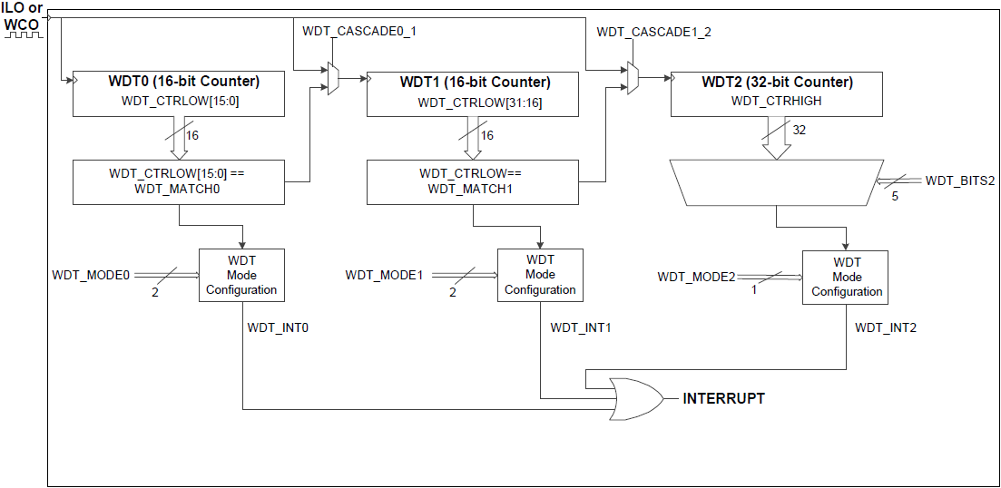
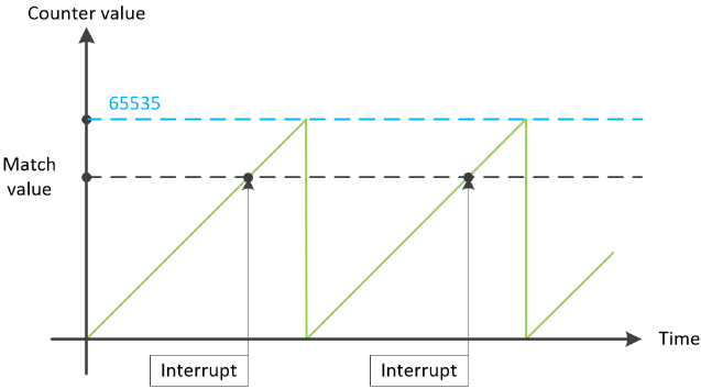
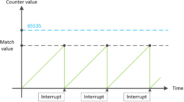
The frequency of the periodic interrupts for C0 and C1 counters can be configured using the Match value using Cy_WDC_SetMatch() together with Clear on match option, which can be set using Cy_WDC_SetClearOnMatch() function. When Clear on match option is not set, the periodic interrupts of the C0 and C1 16-bit sub-counters occur after 65535 counts and the match value defines the shift between interrupts (see the figure below). The enabled Clear on match option resets the counter when the interrupt occurs.
Clear on match is disabled:
Clear on match is enabled:
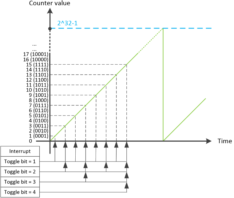
32-bit sub-counter C2 does not have the Clear on match option. The interrupt of counter C2 occurs when the counts equal 2Toggle bit value. For example: when toggle bit = 0, C2 will generate interrupt every WDC clock source rising edge; when toggle bit = 31, C2 will generate interrupt every 231 WDC clock source rising edge.
WDC initialization can be divided into a number of sequential steps listed below:
To set up a WDC, provide the configuration parameters in the cy_stc_wdc_config_t structure. Then call Cy_WDC_Init() to initialize the driver.
The WDC counter can be cascaded in order to achieve longer wait periods. When a counter is cascaded, it uses the previous counter event signal in order to perform the increment operation instead of the WDC clock source. For example, to configure a WDC to generate interrupts approx. every 20 seconds using ILO clock source (40KHz), the total timer period should be set to 40000 * 20 = 800000 counts, which is above the 16-bit single timer resolution. For a long period delays, 32-bit counter 2 can be used, but it only allows fixed period values. In our case, it will generate interrupts with 13.1 seconds (2^19 = 524288) or 26.2 seconds (2^20 = 1048576) periods. To achieve higher timing precision, counters 0 and 1 can be cascaded. In this case, the following configuration structure can be used:
Alternatively, the same settings can be applied using the corresponding WDC functions after calling the Cy_WDC_Init function. Refer to Functions for details.
There are four possible cascading options:
All counter interrupts are OR'd together to form a single combined WDC interrupt. To configure a WDC interrupt, initialize the referenced interrupt by setting the priority and the interrupt vector using Cy_SysInt_Init() of the SysInt driver and provide interrupt handler:
Additionally, global interrupts should be enabled.
The last configuration step enables the configured counters using Cy_WDC_Enable function.
For detail on the WDC peripheral, refer to the technical reference manual (TRM).
| Version | Changes | Reason for Change |
|---|---|---|
| 1.0.2 | Update the paths to the code snippets. | PDL structure update. |
| 1.0.1 | Corrected source code comments text. | |
| 1.0 | Initial version |