|
CAT2 Peripheral Driver Library
|
|
CAT2 Peripheral Driver Library
|
The Watchdog timer (WDT) has a 16-bit (or 32-bit resolution for PSOC4 HVMS/PA devices) free-running up-counter with programmable limit values. More...
Modules | |
| Macros | |
| Enumerated Types | |
| Functions | |
The Watchdog timer (WDT) has a 16-bit (or 32-bit resolution for PSOC4 HVMS/PA devices) free-running up-counter with programmable limit values.
The functions and other declarations used in this driver are in cy_wdt.h. You can include cy_pdl.h to get access to all functions and declarations in the PDL.
The WDT can issue counter match interrupts, and a device reset if its interrupts are not handled. Use the Watchdog timer for two main purposes:
The First use case is recovering from a CPU or firmware failure. A timeout period is set up in the Watchdog timer, and if a timeout occurs, the device is reset (WRES).
The Second use case is to generate periodic interrupts.
You can use the WDT to generate periodic interrupts. However, the Internal Low-Speed Oscillator (ILO) (or Low-Frequency Clock for PSOC4 HVMS/PA devices) is the clock source for the WDT, so its accuracy should be considered. Use the ILO compensation (Cy_SysClk_IloCompensate()) technique to increase ILO accuracy or use Clock Calibration together with Clock Trim (IMO, PILO) technique to increase Low-Frequency Clock accuracy for PSOC4 HVMS/PA devices.
Other options may provide a more precise periodic interrupt. See WDC (Watchdog Counters) (using Watch Crystal Oscillator (WCO) as clock source) or SysTick (ARM System Timer) (in active power mode).
A "reset cause" register exists, and the firmware should check this register at a start-up Cy_SysLib_GetResetReason(). An appropriate action can be taken if a WRES reset is detected.
The user's firmware periodically resets the timeout period (clears or "feeds" the watchdog) before a timeout occurs. If the firmware fails to do so, that is considered to be a CPU crash or a firmware failure, and the reason for a device reset. The WDT can generate an interrupt instead of a device reset. The Interrupt Service Routine (ISR) can handle the interrupt either as a periodic interrupt, or as an early indication of a firmware failure and respond accordingly. However, it is not recommended to use the WDT for periodic interrupt generation. The WDC (Watchdog Counters) can be used to generate periodic interrupts if such are presented in the device.
Functional Description
The WDT generates an interrupt when the count value in the counter equals the configured match value.
Note that the counter is not reset on a match. In such case the WDT reset period is: WDT_Reset_Period = ILO_Period * (2*2^(16-IgnoreBits) + MatchValue); When the counter reaches a match value, it generates an interrupt and then keeps counting up until it overflows and rolls back to zero and reaches the match value again, at which point another interrupt is generated.
To use a WDT to generate a periodic interrupt, the match value should be incremented in the ISR. As a result, the next WDT interrupt is generated when the counter reaches a new match value.
You can also reduce the entire WDT counter period by specifying the number of most significant bits that are ignored in the WDT counter. For example, if the Cy_WDT_SetIgnoreBits() function is called with parameter 3, the WDT counter becomes a 13-bit free-running up-counter.
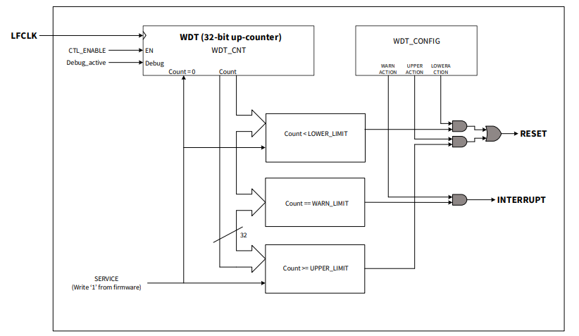
PSOC4 HVMS/PA Functional Design Details
For PSOC4 HVMS/PA devices, the WDT can be configured to act on different counter limits where a reset is triggered if the watchdog is not serviced before the upper limit. In the window mode, a reset is triggered if the servicing occurs before the lower limit is reached. The warning limit triggers an interrupt to request servicing. Each of these actions can be activated independently. The WDT is enabled and specific registers are locked by default. An unlocking sequence is required to prevent accidental accesses. The WDT operates in active, sleep, and deepsleep modes. After a WDT reset the device returns to active mode.
Register Locking
You can prevent accidental corruption of the WDT configuration by calling the Cy_WDT_Lock() function. When the WDT is locked, any writing to the WDT_*, CLK_ILO_CONFIG, CLK_SELECT.LFCLK_SEL, and CLK_TRIM_ILO_CTL registers is ignored. Call the Cy_WDT_Unlock() function to allow registers modification, mentioned above.
Power Modes
WDT can operate in all possible low power modes.
In CPU Active mode, an interrupt request from the WDT is sent to the CPU. In CPU Sleep, CPU Deep Sleep mode, the CPU subsystem is powered down, so the interrupt request from the WDT is sent directly to the WakeUp Interrupt Controller (WIC) which will then wake up the CPU. The CPU then acknowledges the interrupt request and executes the ISR.
Clock Source
The WDT is clocked by the ILO (or Low-Frequency Clock for PSOC4 HVMS/PA devices). The WDT must be disabled before disabling the ILO (or Low-Frequency Clock). Need to consider ILO (or Low-Frequency Clock) accuracy while configuring WDT intervals to make sure that unwanted device resets do not occur on some devices.
Refer to the device datasheet for more information on the oscillator accuracy.
Clearing WDT
The ILO (or Low-Frequency Clock) clock is asynchronous to the SysClk. Therefore it generally takes three ILO (or Low-Frequency Clock) cycles for WDT register changes to come into effect. It is important to remember that a WDT should be cleared at least four cycles (3 + 1 for sure) before a timeout occurs, especially when small match values / low-toggle bit numbers are used.
Reset Detection
Use the Cy_SysLib_GetResetReason() function to detect whether the WDT has triggered a device reset.
Interrupt Configuration
If the WDT is configured to generate an interrupt, pending interrupts must be cleared within the ISR (otherwise, the interrupt will be generated continuously). A pending interrupt to the WDT block must be cleared by calling the Cy_WDT_ClearInterrupt() function. The call to the function will clear the unhandled WDT interrupt counter.
Use the WDT ISR as a timer to trigger certain actions and to change a next WDT match or limit value.
Ensure that the interrupts from the WDT are passed to the CPU to avoid unregistered interrupts. Unregistered WDT interrupts result in a continuous device reset. To avoid this, call Cy_WDT_UnmaskInterrupt(). After that, call the WDT API functions for interrupt handling/clearing.
It is not recommended to reset the watchdog counter in the WDT interrupt service routine (ISR), if WDT is being used as a reset source to protect the system against crashes. If necessary, use the warning interrupt to set a flag in the ISR. Local processing loops can observe that flag and break out of their loop. This allows the main loop to reach the servicing code (and clear the flag for the next pass through the main loop).
To start the WDT, make sure that ILO (or Low-Frequency Clock) is enabled. After the ILO (or Low-Frequency Clock) is enabled, ensure that the watchdog reset is disabled by calling the Cy_WDT_Disable() function. Set the WDT match value by calling Cy_WDT_SetMatch() with the required match value. If needed, set the ignore bits for reducing the WDT counter period by calling Cy_WDT_SetIgnoreBits() function. After the WDT configuration is set, call Cy_WDT_Enable().
When the WDT is used to protect against system crashes, the WDT interrupt should be cleared by a portion of the code that is not directly associated with the WDT interrupt. Otherwise, it is possible that the main firmware loop has crashed or is in an endless loop, but the WDT interrupt vector continues to operate and service the WDT. The user should:
Set parameters of the WDT.
Create an interrupt config structure and interrupt handler.
Hook the interrupt service routine and enable interrupt than config the WDT.
In this case, the WDT resets every third WDT event of the system(1.2287s at ILO 40kHz).
As part of this code, the snippet uses the formula from the Functional Description .
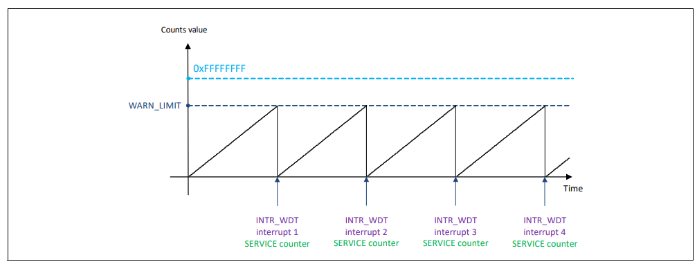
The timing diagram below shows the behavior of the WDT counter in interrupt mode. LOWER and UPPER actions are disabled. An interrupt is issued each time the counter matches the WARN_LIMIT. The interrupt period is calculated by 2^32 x LFCLK clock cycles. The WDT counter could be cleared (serviced) in two ways:
Set parameters of the WDT.
Create an interrupt config structure and interrupt handler.
Hook the interrupt service routine and enable interrupt than config the WDT.
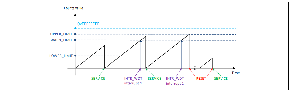
The timing diagram below shows the behavior of the WDT counter in window mode. The timing diagram shows all scenarios of the WDT operation while LOWER_ACTION, WARN_ACTION, and UPPER_ACTION are enabled.
For more information on the WDT peripheral, refer to the technical reference manual (TRM).
| Version | Changes | Reason for Change |
|---|---|---|
| 1.10 | Added support for PSOC4 HVMS/PA platform. Updated APIs to incorporate PSOC4 HVMS/PA platform configuration. Documentation enhancement. Provided code snippets. | New device support. |
| 1.0.3 | Updated code snippets. | Documentation enhancement. |
| 1.0.2 | Update the paths to the code snippets. | PDL structure update. |
| 1.0.1 | Code snippets added. | Documentation enhancement. |
| 1.0 | Initial version |