|
PSOC E8XXGP Device Support Library
|
|
PSOC E8XXGP Device Support Library
|
Driver API for EZI2C Slave Peripheral.
The functions and other declarations used in this part of the driver are in cy_scb_ezi2c.h. You can also include cy_pdl.h to get access to all functions and declarations in the PDL.
I2C - The Inter-Integrated Circuit (I2C) bus is an industry-standard.
The EZI2C slave peripheral driver provides an API to implement the I2C slave device based on the SCB hardware block. This slave device emulates a common I2C EEPROM interface that acts like dual-port memory between the external master and your code. I2C devices based on the SCB hardware are compatible with the I2C Standard mode, Fast mode, and Fast mode Plus specifications, as defined in the I2C bus specification.
EZI2C slave is a special implementation of the I2C that handles all communication between the master and slave through ISR (interrupt service routine) and requires no interaction with the main program flow from the slave side. The EZI2C should be used when a shared memory model between the I2C master and I2C slave is needed.
Features:
The EZI2C slave driver configuration can be divided to number of sequential steps listed below:
To set up the EZI2C slave driver, provide the configuration parameters in the cy_stc_scb_ezi2c_config_t structure. The primary slave address slaveAddress1 must be provided. The other parameters are optional for operation. To initialize the driver, call Cy_SCB_EZI2C_Init function providing a pointer to the populated cy_stc_scb_ezi2c_config_t structure and the allocated cy_stc_scb_ezi2c_context_t structure.
Set up the EZI2C slave buffer before enabling its operation by using Cy_SCB_EZI2C_SetBuffer1 for the primary slave address and Cy_SCB_EZI2C_SetBuffer2 for the secondary (if the secondary is enabled).
Only dedicated SCB pins can be used for I2C operation. The HSIOM register must be configured to connect dedicated SCB I2C pins to the SCB block. Also the I2C pins must be configured in Open-Drain, Drives Low mode (this pin configuration implies usage of external pull-up resistors):
A clock source must be connected to the SCB block to oversample input and output signals, in this document this clock will be referred as clk_scb. You must use one of the 8-bit or 16-bit dividers. Use the SysClk (System Clock) driver API to do this.
To get EZI2C slave to operate at the desired data rate, the clk_scb must be fast enough to provide sufficient oversampling. Use the SysClk (System Clock) driver API to do this.
Refer to the technical reference manual (TRM) section I2C sub-section Oversampling and Bit Rate to get information about how to configure the I2C to run at the desired data rate.
The interrupt is mandatory for the EZI2C slave operation. The Cy_SCB_EZI2C_Interrupt function must be called in the interrupt handler for the selected SCB instance. Also, this interrupt must be enabled in the NVIC or it will not work.
Finally, enable the EZI2C slave operation by calling Cy_SCB_EZI2C_Enable. Now the I2C device responds to the assigned address.
The EZI2C slave operation might not require calling any EZI2C slave function because the I2C master is able to access the slave buffer. The application can directly access it as well. Note that this is an application-level task to ensure the buffer content integrity.
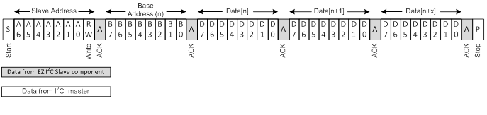
This operation starts with sending a base address that is one or two bytes, depending on the sub-address size configuration. This base address is retained and will be used for later read operations. Following the base address, there is a sequence of bytes written into the buffer starting from the base address location. The buffer index is incremented for each written byte, but this does not affect the base address that is retained. The length of a write operation is limited by the maximum buffer read/write region size.
When a master attempts to write outside the read/write region or past the end of the buffer, the last byte is NACKed.
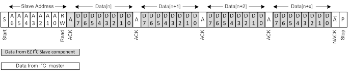
This operation always starts from the base address set by the most recent write operation. The buffer index is incremented for each read byte. Two sequential read operations start from the same base address no matter how many bytes are read. The length of a read operation is not limited by the maximum size of the data buffer. The EZI2C slave returns 0xFF bytes if the read operation passes the end of the buffer.
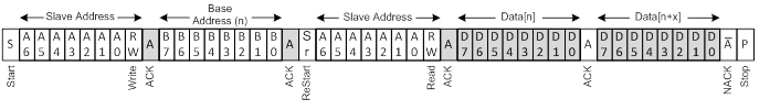
Typically, a read operation requires the base address to be updated before starting the read. In this case, the write and read operations must be combined together.
The I2C master may use the ReStart or Stop/Start conditions to combine the operations. The write operation sets only the base address and the following read operation will start from the new base address. In cases where the base address remains the same, there is no need for a write operation.
The EZI2C slave provides the callback functions to handle power mode transition. The callback Cy_SCB_EZI2C_DeepSleepCallback must be called during execution of Cy_SysPm_CpuEnterDeepSleep; Cy_SCB_EZI2C_HibernateCallback must be called during execution of Cy_SysPm_SystemEnterHibernate. To trigger the callback execution, the callback must be registered before calling the power mode transition function. Refer to SysPm (System Power Management) driver for more information about power mode transitions and callback registration.
The EZI2C configured to support two addresses can wakeup the device on address match to NACK not supported address. This happens because the hardware address-match-logic uses address bit masking to support to two addresses. The address mask defines which bits in the address are treated as non-significant while performing an address match. One non-significant bit results in two matching addresses; two bits will match 4 and so on. If the two addresses differ by more than a single bit, then the extra addresses that will pass the hardware match and wakeup the device from Deep Sleep mode. Then firmware address matching will to generate a NAK. Due to this reason, it is preferable to select a secondary address that is different from the primary by one bit. The address mask in this case makes one bit non-significant. For example:
API Reference | |
| Macros | |
| Functions | |
| Data Structures | |
| Enumerated Types | |