PSoC 6 Peripheral Driver Library
CAN FD (CAN with Flexible Data-Rate)

General Description

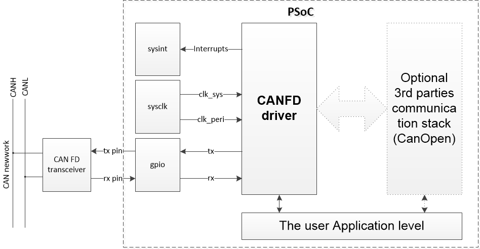
The CAN FD driver provides an easy method to access the CAN FD IP block registers and provides simple functionality for sending and receiving data between devices in the CAN FD network.

The CAN FD driver provides an API to configure the main features - mode, bit time, message buffers - and transmit and receive message in all modes:

canfd_solution.png
CAN FD Solution

Configuration Considerations

Specification of the sample code is as follows:

Use ModusToolbox Device Configurator Tool to generate initialization code

The steps to generate initialization code using the ModusToolbox Device Configurator Tool:

  1. Launch the ModusToolbox Device Configurator Tool.
  2. Switch to the Peripherals tab. Enable the CAN FD channel personality under Communication and enter Alias (default is canfd_0_chan_0).
  3. Go to the Parameters Pane for the CAN FD Personality and configure it with the desired parameters (set the Clock Signal divider, set the bit timing configuration, set the other parameters per Configuration Considerations, etc).
  4. Perform File->Save for the initialization code to generate.

Now, all required CAN FD initialization code and configuration prerequisites will be generated:

For the CAN FD interrupt service routine, Cy_CANFD_IrqHandler() can be used. It handles reading data from the dedicated RX buffers and RX FIFO buffers. Corresponding callback functions are called for error interrupts, RX interrupts and TX complete interrupt. Put the names of callback functions to the Callback functions parameters section. Put NULL if no callback function to be used.

Note
Only RX interrupt sources are enabled by default. Use Cy_CANFD_SetInterruptMask() to enable other interrupt sources.
Interrupt flags are set regardless of the interrupt enable register. Cy_CANFD_IrqHandler will check and process all supported interrupts when triggered with any enabled interrupt source.
/* CANFD interrupt handler */
void CanfdInterruptHandler(void)
{
/* Just call the IRQ handler with the current channel number and context */
Cy_CANFD_IrqHandler(CANFD0, 0, &context);
}

Set up the interrupt handler to be called with CAN FD events. The CAN FD block has two interrupt lines which can be assigned to different interrupt sources using Cy_CANFD_SetInterruptLine(): canfd_0_interrupts0_0_IRQn and canfd_0_interrupts1_0_IRQn. Also, the CAN FD block has a consolidated interrupt canfd_0_interrupt0_IRQn. The following code shows how to set up the interrupt handler.

/* Setup the CANFD interrupt */
{
/* Populate the configuration structure */
const cy_stc_sysint_t irq_cfg =
{
/* .intrSrc */ canfd_0_interrupts0_0_IRQn, /* CAN FD interrupt number */
/* .intrPriority */ 3UL
};
/* Hook the interrupt service routine and enable the interrupt */
(void) Cy_SysInt_Init(&irq_cfg, &CanfdInterruptHandler);
NVIC_EnableIRQ(canfd_0_interrupts0_0_IRQn);
}

Implement the initialization code manually

Call Cy_CANFD_Init() to initialize the CAN FD module. It initializes the CAN FD module with the configuration parameters, passed in the cy_stc_canfd_config_t structure. It consists of several elements to be defined first.

const cy_stc_canfd_config_t config =
{
/* .txCallback */ NULL,
/* .rxCallback */ CAN_RxMsgCallback,
/* .errorCallback */ NULL,
/* .canFDMode */ true,
/* .bitrate */ &bitrateConfig,
/* .fastBitrate */ &fastBitrateConfig,
/* .tdcConfig */ &tdcConfig,
/* .sidFilterConfig */ &sidFiltersConfig,
/* .extidFilterConfig */ &extidFiltersConfig,
/* .globalFilterConfig */ &globalFilterConfig,
/* .rxBufferDataSize */ CY_CANFD_BUFFER_DATA_SIZE_64,
/* .rxFIFO1DataSize */ CY_CANFD_BUFFER_DATA_SIZE_64,
/* .rxFIFO0DataSize */ CY_CANFD_BUFFER_DATA_SIZE_64,
/* .txBufferDataSize */ CY_CANFD_BUFFER_DATA_SIZE_64,
/* .rxFIFO0Config */ &rxFifo0Config,
/* .rxFIFO1Config */ &rxFifo1Config,
/* .noOfRxBuffers */ 0x4u,
/* .noOfTxBuffers */ 0x2u,
/* .messageRAMaddress */ CY_CAN0MRAM_BASE,
/* .messageRAMsize */ 4096u
};

The Cy_CANFD_Init() function also initializes the shared context structure used later with other API functions.

cy_stc_canfd_context_t context; /* This is a shared context structure,
* unique for each channel
*/

Although the callback functions are optional, they are recommended for use, otherwise, there is no report to the API about any error and transmission or reception events. The example callback function sends received data back to the bus, incrementing ID by 1:

/* CANFD reception callback */
void CAN_RxMsgCallback(bool bRxFifoMsg, uint8_t u8MsgBufOrRxFifoNum,
cy_stc_canfd_rx_buffer_t* pstcCanFDmsg)
{
if(0 == pstcCanFDmsg->r0_f->rtr) /* Only for data frames */
{
/* Sets up the CANFD TX Buffer for response */
cy_stc_canfd_t0_t t0registerMsg0 =
{
/* id */ pstcCanFDmsg->r0_f->id + 1, /* Message ID is incremented*/
/* xtd */ pstcCanFDmsg->r0_f->xtd,
};
cy_stc_canfd_t1_t t1registerMsg0 =
{
/* dlc */ pstcCanFDmsg->r1_f->dlc,
/* brs */ true,
/* efc */ false,
/* mm */ 0UL
};
{
/* t0_f */ &t0registerMsg0,
/* t1_f */ &t1registerMsg0,
/* data_area_f */ pstcCanFDmsg->data_area_f
};
/* Sends the same message back with an incremented ID */
Cy_CANFD_UpdateAndTransmitMsgBuffer(CANFD0, 0UL, &txBuffer, 0u, &context);
}
/* These parameters are not used in this snippet */
(void)bRxFifoMsg;
(void)u8MsgBufOrRxFifoNum;
}

CAN FD IP block requires the configuration of a peripheral clock divider. The following code configures an 8-bit clock divider. The default peripheral clock frequency is 72 MHz. The desired divider value minus one must be passed.

/* Setup CAN clock (cclk).
* This clock is used as base clock of the CAN communication.
* Use divider 3 for 24MHz
* Use divider 9 for 8MHz
*/
#define DIVIDER_INDEX 0u
#define DIVIDER_VALUE (9u - 1u) /* One less than divider value must be used */
Cy_SysClk_PeriphAssignDivider(PCLK_CANFD0_CLOCK_CAN0, CY_SYSCLK_DIV_8_BIT, DIVIDER_INDEX);
Cy_SysClk_PeriphSetDivider(CY_SYSCLK_DIV_8_BIT, DIVIDER_INDEX, DIVIDER_VALUE);

The CAN FD block uses the Port 5 pins for receive (P5[0]) and transmit (P5[1]).

/* Assign pins for CAN FD RX and TX: P5[0] and P5[1]. */
#define CANFD_PORT (P5_0_PORT)
#define CANFD_RX_NUM (P5_0_NUM)
#define CANFD_TX_NUM (P5_1_NUM)
Cy_GPIO_SetHSIOM(CANFD_PORT, CANFD_RX_NUM, P5_0_CANFD0_TTCAN_RX0);
Cy_GPIO_SetHSIOM(CANFD_PORT, CANFD_TX_NUM, P5_1_CANFD0_TTCAN_TX0);
Cy_GPIO_SetDrivemode(CANFD_PORT, CANFD_RX_NUM, CY_GPIO_DM_HIGHZ);
Cy_GPIO_SetDrivemode(CANFD_PORT, CANFD_TX_NUM, CY_GPIO_DM_STRONG);

For the CANFD interrupt service routine, the Cy_CANFD_IrqHandler() can be used. It handles reading data from dedicated RX buffers and RX FIFO buffers. Corresponding callback functions are called for error interrupts, RX interrupts and TX complete interrupt.

Note
Only RX interrupt sources are enabled by default. Use Cy_CANFD_SetInterruptMask() to enable other interrupt sources.
Interrupt flags are set regardless of the interrupt enable register. Cy_CANFD_IrqHandler will check and process all supported interrupts when triggered with any enabled interrupt source.
/* CANFD interrupt handler */
void CanfdInterruptHandler(void)
{
/* Just call the IRQ handler with the current channel number and context */
Cy_CANFD_IrqHandler(CANFD0, 0, &context);
}

Setup the interrupt handler to be called with the CAN FD events. The CAN FD block has two interupt lines, which can be assigned to different interrupt sources using Cy_CANFD_SetInterruptLine(): canfd_0_interrupts0_0_IRQn and canfd_0_interrupts1_0_IRQn. Also, the CAN FD block has a consolidated interrupt canfd_0_interrupt0_IRQn. The following code shows how to set up the interrupt handler.

/* Setup the CANFD interrupt */
{
/* Populate the configuration structure */
const cy_stc_sysint_t irq_cfg =
{
/* .intrSrc */ canfd_0_interrupts0_0_IRQn, /* CAN FD interrupt number */
/* .intrPriority */ 3UL
};
/* Hook the interrupt service routine and enable the interrupt */
(void) Cy_SysInt_Init(&irq_cfg, &CanfdInterruptHandler);
NVIC_EnableIRQ(canfd_0_interrupts0_0_IRQn);
}

CAN FD has two bit rate settings, for arbitration and data phases. Both are configured with the same structure, containing a pre-scaler, time segment 1, time segment 2 and synchronization jump width.

Note
The actual interpretation by the hardware of configured values is one more value than programmed.
The bit rate configured for the CAN FD data phase must be higher or equal to the bit rate configured for the arbitration phase.

The CAN time quantum (tq) may be programmed in the range of 1 to 32 CAN FD clock periods: tq = (prescaler + 1) mtq, where mtq is CAN FD block's clock period. The length of the bit time is (programmed values) [timeSegment1 + timeSegment2 + 3] tq.
The example below shows the configuration with the 100 kbps arbitration bit rate and 200 kbps data bit rate. This assumes the peripheral clock frequency of 72 MHz divided by 9 to obtain the 8 MHz clock for the CAN FD block.

cy_stc_canfd_bitrate_t bitrateConfig =
{
/* .prescaler */ 10u - 1u, /* 0 to 511 */
/* .timeSegment1 */ 5u - 1u, /* 0 to 255 */
/* .timeSegment2 */ 2u - 1u, /* 0 to 127 */
/* .syncJumpWidth */ 2u - 1u /* 0 to 127 */
};
cy_stc_canfd_bitrate_t fastBitrateConfig =
{
/* .prescaler */ 5u - 1u, /* 0 to 511 */
/* .timeSegment1 */ 5u - 1u, /* 0 to 255 */
/* .timeSegment2 */ 2u - 1u, /* 0 to 127 */
/* .syncJumpWidth */ 2u - 1u /* 0 to 127 */
};
{
/* .tdcEnabled */ false,
/* .tdcOffset */ 0,
/* .tdcFilterWindow */ 0
};

CAN FD driver provides API to setup Message ID filtering. There are standard ID and extended ID filters. The desired count of the filters of each type is specified in the cy_stc_canfd_config_t structure and is set once during block initialization. It is possible to change the configured filters settings with Cy_CANFD_SidFilterSetup() and Cy_CANFD_XidFilterSetup(). Use the cy_stc_id_filter_t structure to set up one standard ID filter:

#define MESSAGE_ID0 (0x00000001UL)
#define MESSAGE_ID1 (0x00000010UL)
#define MESSAGE_ID2 (0x00000020UL)
#define MESSAGE_ID3 (0x00010010UL)
#define RX_BUFFER_ELEMENT_1 (0x0UL)
#define RX_BUFFER_ELEMENT_2 (0x1UL)
#define RX_BUFFER_ELEMENT_3 (0x2UL)
#define RX_BUFFER_ELEMENT_4 (0x3UL)
static const cy_stc_id_filter_t stdIdFilters[] =
{
/* stdIdFilter[0] */
{
/* .sfid2 */ RX_BUFFER_ELEMENT_1,
/* .sfid1 */ MESSAGE_ID0,
},
/* stdIdFilter[1] */
{
/* .sfid2 */ RX_BUFFER_ELEMENT_2,
/* .sfid1 */ MESSAGE_ID1,
/* .sft */ CY_CANFD_SFT_CLASSIC_FILTER
}
};
{
/* .numberOfSIDFilters */ sizeof(stdIdFilters) / sizeof(stdIdFilters[0]),
/* .sidFilter */ stdIdFilters,
};

Use the cy_stc_extid_filter_t structure to set up an extended ID filter:

cy_stc_canfd_f0_t filter0F0Config =
{
/* .efid1 */ MESSAGE_ID2,
};
cy_stc_canfd_f1_t filter0F1Config =
{
/* .efid2 */ RX_BUFFER_ELEMENT_3,
};
cy_stc_canfd_f0_t filter1F0Config =
{
/* .efid1 */ MESSAGE_ID3,
};
cy_stc_canfd_f1_t filter1F1Config =
{
/* .efid2 */ RX_BUFFER_ELEMENT_4,
/* .eft */ CY_CANFD_EFT_CLASSIC_FILTER
};
const cy_stc_extid_filter_t extIdFilters[] =
{
/* extIdFilter[0] */
{
/* .f0_f */ &filter0F0Config,
/* .f1_f */ &filter0F1Config
},
/* extIdFilter[1] */
{
/* .f0_f */ &filter1F0Config,
/* .f1_f */ &filter1F1Config
}
};
{
/* numberOfEXTIDFilters */ sizeof(extIdFilters) / sizeof(extIdFilters[0]),
/* extidFilter */ extIdFilters,
/* extIDANDMask */ 0x1fffffffUL
};

Message IDs that do not match any filter are received according to the global filter set up. The global filter can be set up to receive messages with standard and extended IDs to different FIFO buffers. It can be configured to reject remote frames, as shown below.

{
/* .nonMatchingFramesStandard */ CY_CANFD_ACCEPT_IN_RXFIFO_0,
/* .nonMatchingFramesExtended */ CY_CANFD_ACCEPT_IN_RXFIFO_1,
/* .rejectRemoteFramesStandard */ true,
/* .rejectRemoteFramesExtended */ true
};

The RX FIFO buffers, FIFO 0 and FIFO 1 are configured once on block initialization using cy_en_canfd_fifo_config_t structure.

cy_en_canfd_fifo_config_t rxFifo0Config =
{
/* watermark */ 0u,
/* numberOfFifoElements */ 1u,
/* topPointerLogicEnabled */ false
};
cy_en_canfd_fifo_config_t rxFifo1Config =
{
/* watermark */ 0u,
/* numberOfFifoElements */ 1u,
/* topPointerLogicEnabled */ false
};

The cy_stc_canfd_config_t structure is used to pass all configuration to Cy_CANFD_Init() function. It is populated with pointers to other structures required and constants, defined before.

const cy_stc_canfd_config_t config =
{
/* .txCallback */ NULL,
/* .rxCallback */ CAN_RxMsgCallback,
/* .errorCallback */ NULL,
/* .canFDMode */ true,
/* .bitrate */ &bitrateConfig,
/* .fastBitrate */ &fastBitrateConfig,
/* .tdcConfig */ &tdcConfig,
/* .sidFilterConfig */ &sidFiltersConfig,
/* .extidFilterConfig */ &extidFiltersConfig,
/* .globalFilterConfig */ &globalFilterConfig,
/* .rxBufferDataSize */ CY_CANFD_BUFFER_DATA_SIZE_64,
/* .rxFIFO1DataSize */ CY_CANFD_BUFFER_DATA_SIZE_64,
/* .rxFIFO0DataSize */ CY_CANFD_BUFFER_DATA_SIZE_64,
/* .txBufferDataSize */ CY_CANFD_BUFFER_DATA_SIZE_64,
/* .rxFIFO0Config */ &rxFifo0Config,
/* .rxFIFO1Config */ &rxFifo1Config,
/* .noOfRxBuffers */ 0x4u,
/* .noOfTxBuffers */ 0x2u,
/* .messageRAMaddress */ CY_CAN0MRAM_BASE,
/* .messageRAMsize */ 4096u
};

The Cy_CANFD_Init() function initializes the CAN FD block by writing CAN FD configuration registers. Cy_CANFD_Init() enables the RX interrupts for new message reception into the dedicated RX buffers, FIFO 0 and FIFO 1. The code example also shows the test mode configuration which can be used to enable the Loopback mode. See cy_stc_canfd_test_mode_t for details. Cy_CANFD_Init() sets test mode configuration to CY_CANFD_TEST_MODE_DISABLE. Remember to disable the echo functionality in the RX callback when using a loopback.

if(CY_CANFD_SUCCESS != Cy_CANFD_Init (CANFD0, 0, &config, &context))
{
/* Error processing */
}
/* Enables the configuration changes to set Test mode */
/* Sets the Test mode configuration */
/* Disables the configuration changes */

To send a CAN FD message, a TX buffer structure must be prepared which consists of the T0 and T1 registers and data array.

/* Prepares a CANFD message to transmit */
/* Sets up the CANFD TX Buffer */
cy_stc_canfd_t0_t t0registerMsg0 =
{
/* id */ 0x200,
};
cy_stc_canfd_t1_t t1registerMsg0 =
{
/* dlc */ 15U,
/* brs */ true,
/* efc */ false,
/* mm */ 0UL
};
{
/* t0_f */ &t0registerMsg0,
/* t1_f */ &t1registerMsg0,
/* data_area_f */ data
};
/* Prepare data to send */
data[0] = 0x78563412UL;
data[1] = 0x11111111UL;
data[2] = 0x22222222UL;
data[3] = 0x33332222UL;
data[4] = 0x55554444UL;
data[5] = 0x77776666UL;
data[6] = 0x99998888UL;
data[7] = 0xBBBBAAAAUL;
data[8] = 0xDDDDCCCCUL;
data[9] = 0xFFFFEEEEUL;
data[10] = 0x78563412UL;
data[11] = 0x00000000UL;
data[12] = 0x11111111UL;
data[13] = 0x22222222UL;
data[14] = 0x33333333UL;
data[15] = 0x44444444UL;

To transmit CAN FD messages, the function Cy_CANFD_UpdateAndTransmitMsgBuffer() is used. The buffer status can be retrieved by Cy_CANFD_GetTxBufferStatus(). It is possible to set a callback function which will be notified whenever a message transmission has been completed.

for(;;)
{
/* Sends the prepared data using tx buffer 1 and waits for 1000ms */
Cy_CANFD_UpdateAndTransmitMsgBuffer(CANFD0, 0u, &txBuffer, 1u, &context);
}

More Information

For more information on the CAN FD peripheral, refer to the technical reference manual (TRM).

MISRA-C Compliance

The CAN FD driver does not have any specific deviations.

Changelog

VersionChangesReason for Change
1.10 Updated of the Cy_CANFD_Init() functions Allow initing CANFD with 0 number of SID/XID filters
1.0.1 Updated description of the Cy_CANFD_Init() and Cy_CANFD_DeInit() functions Documentation update and clarification
1.0 Initial version

API Reference

 Macros
 This section describes the CAN FD Macros.
 
 Functions
 
 Data Structures
 
 Enumerated Types