This section provides a guide to quickly get started with the PMBus middleware. Namely: how to set up the PMBus middleware in your project, configure the necessary hardware, and implement the basic PMBus controller functionality.
Note: Testing the Controller mode functionality requires a second PMBus device operating in Target mode. Recommended: use the Target Mode Quick Start Guide to set up the PMBus Target device.
1. Add mtb-pmbus middleware to your project
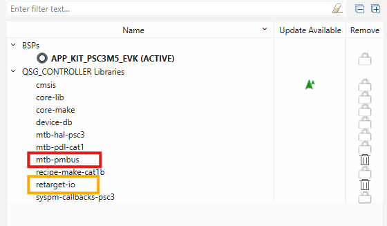
- If you work in the ModusToolbox IDE, use the ModusToolbox Library Manager to add the mtb-pmbus middleware to your project. Otherwise, ensure that mtb-pmbus middleware is included into your project.
Note: Middleware uses printf() for logging purposes. To use printf() for the terminal output, add retarget-io middleware from the Library Manager or in any other way.
2. Configure SCB blocks
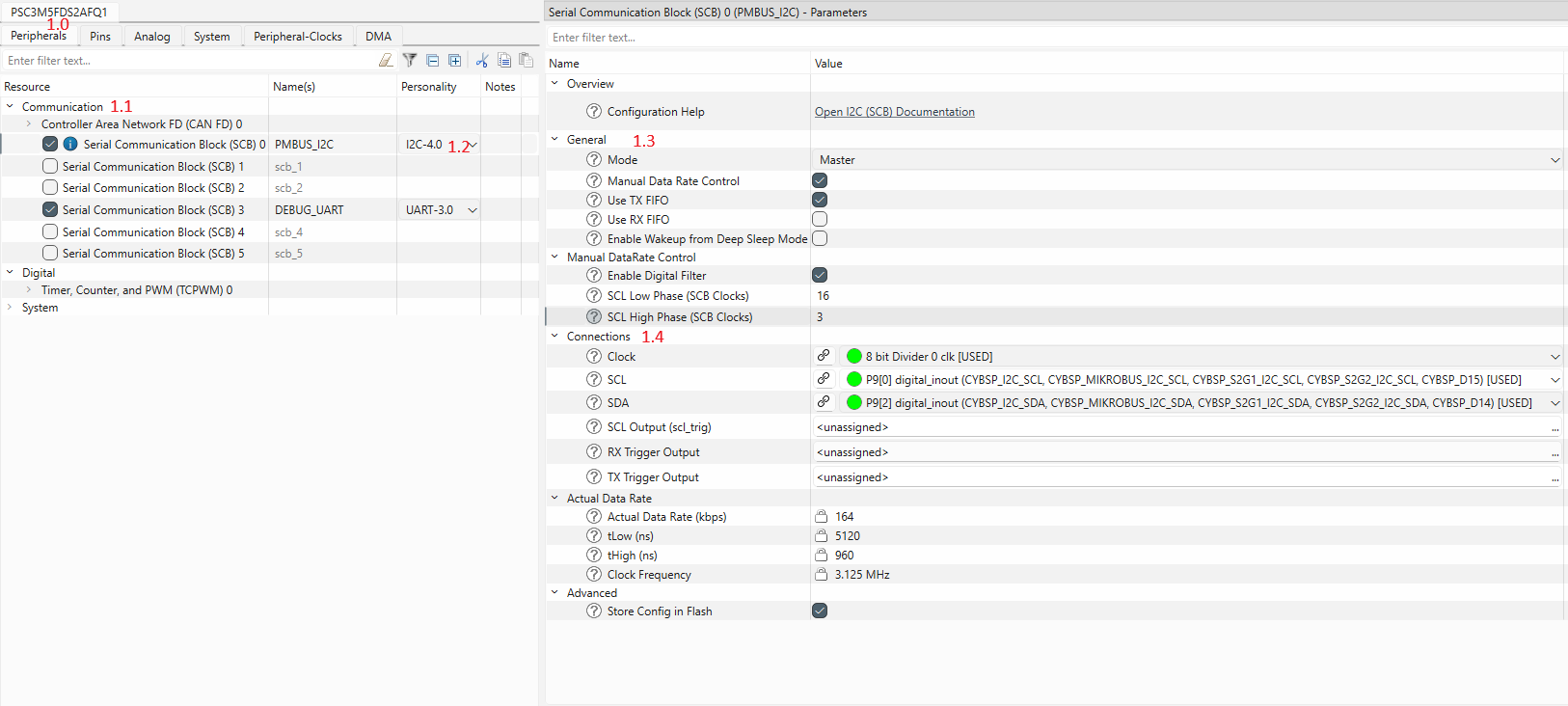
- Open the Device Configurator and go to the Peripherals tab (#1.0).
- Enable the SCB block under Communication (#1.1) and select the I2C Personality (#1.2). Select the desired name for the SCB (e.g., PMBUS_I2C).
- In the "General" section (#1.3), choose Master mode and set the I2C Data Rate to the desired value (e.g., 100 kHz). Disable the "Use RX FIFO".
- In the "Connect" section (#1.4), select:
- the desired Clock for the SCB block
- the desired pins for SDA and SCL lines, the Device Configurator will automatically configure them to Open Drain mode.
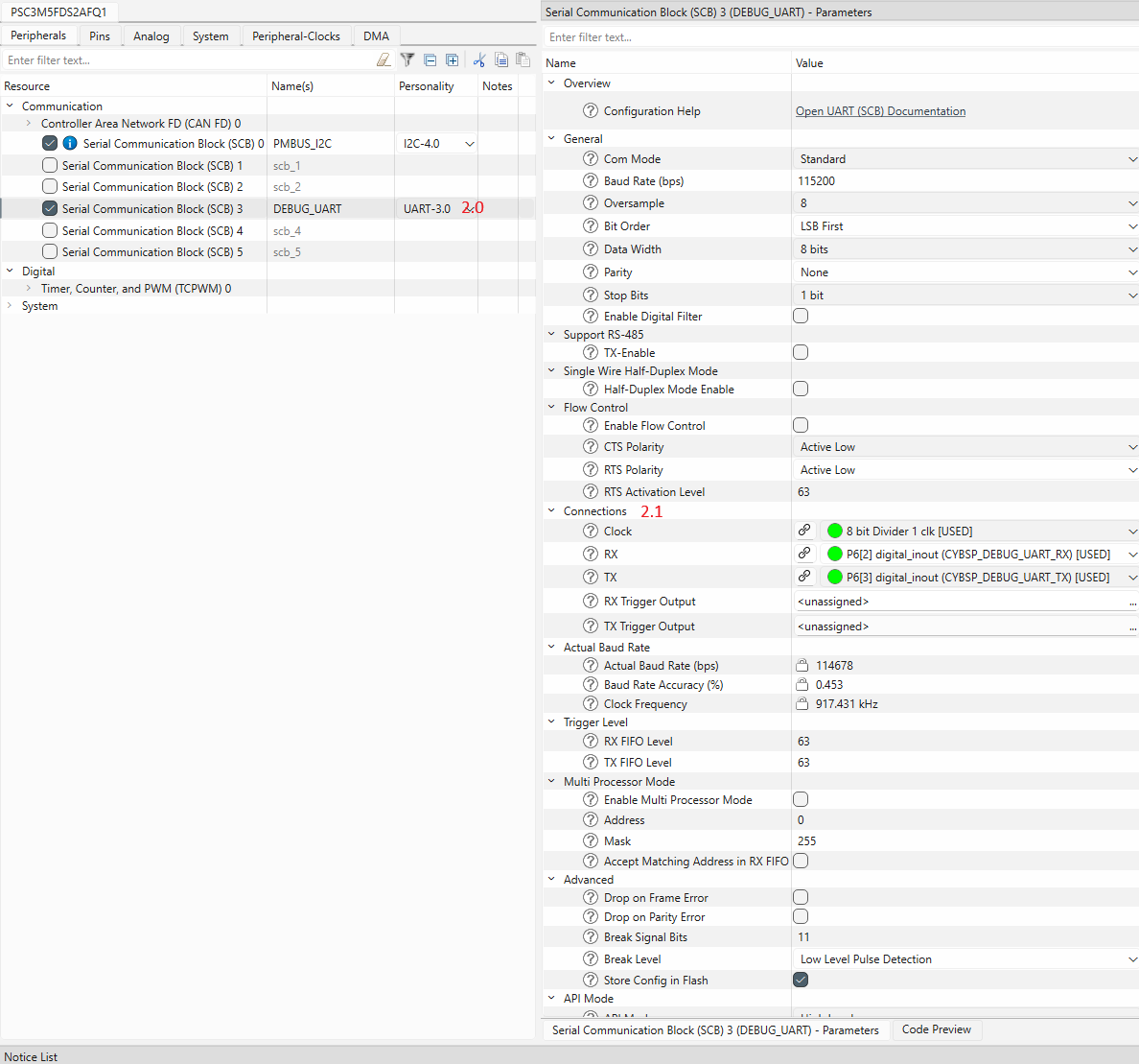
- Enable another SCB block under Communication and select UART Personality (#2.0). Select the desired name for the SCB. This block will be used for the debug output.
- Select the desired pins and clock for the SCB (#2.1). The other UART options can be set by default, see the screenshot.
- Select File->Save to generate initialization code.
3. Add SMBus/PMBus controller code to your project
This section:
- describes the implementation of a PMBus controller device
- demonstrates how to send Quick Command and Read 32 protocols with the CMD1(0x10) command to the PMBus target device by using dedicated protocol APIs
- shows how to use generic transfer API to send Write Byte protocol with PAGE(0x00) command and Write/Read Word with the CMD2(0x11) command.
Step 1. Fill the mtb_pmbus_conf.h file with the desired compile-time configuration macros. This file will appear in the project import folder after adding the mtb-pmbus middleware.
Note: This file is intended only for PMBus configuration without using the Device Configurator and solution personality. To enable this possibility, add define MTB_PMBUS_MANUAL_CONFIG to project Makefile:
DEFINES += MTB_PMBUS_MANUAL_CONFIG
#ifdef MTB_PMBUS_MANUAL_CONFIG
#ifndef MTB_PMBUS_CONF_H
#define MTB_PMBUS_CONF_H
#include "mtb_pmbus_log_level.h"
#define MTB_PMBUS_LOG_LEVEL (MTB_PMBUS_LOG_LEVEL_DEBUG)
#define MTB_PMBUS_ENABLE_TIMEOUT (0U)
#endif
#endif
Step 2. Include the necessary header files into the main.c file:
#include "mtb_pmbus.h"
#include "cybsp.h"
#include "cy_retarget_io.h"
Step 3. Set the project defines:
#define PMBUS_TARGET_ADDRESS (0x18U)
#define PMBUS_PAGE_CMD_CODE (0x00U)
#define PMBUS_TEST_CMD_1_CODE (0x10U)
#define PMBUS_TEST_CMD_2_CODE (0x11U)
#define PMBUS_TEST_PAGE_NUM (0x01U)
#define PMBUS_CTRL_TIMEOUT_US (1000000UL)
Step 4. Create variables for:
Debug the UART HAL object and context:
static cy_stc_scb_uart_context_t DEBUG_UART_context;
static mtb_hal_uart_t DEBUG_UART_hal_obj;
I2C context:
static cy_stc_scb_i2c_context_t i2c_pdl_context;
PMBus controller instance:
Controller instance structure.
Definition mtb_pmbus_ctrl.h:203
Step 5. Implement the I2C interrupt handler function:
void i2c_isr(void)
{
}
void mtb_pmbus_ctrl_isr(mtb_pmbus_ctrl_stc_t *inst)
PMBus controller interrupt service routine.
Definition mtb_pmbus_ctrl_hal.c:51
Step 6. Implement callback functions for controlling I2C hardware resources and enabling/disabling I2C interrupts:
{
{
Cy_SCB_I2C_Init(PMBUS_I2C_HW, &PMBUS_I2C_config, &i2c_pdl_context);
cy_stc_sysint_t i2c_isr_cfg =
{
.intrSrc = PMBUS_I2C_IRQ,
.intrPriority = 3U
};
Cy_SysInt_Init(&i2c_isr_cfg, i2c_isr);
printf("I2C hardware initialized\n\r");
}
{
Cy_SCB_I2C_Enable(PMBUS_I2C_HW);
printf("I2C hardware enabled\n\r");
}
{
Cy_SCB_I2C_Disable(PMBUS_I2C_HW, &i2c_pdl_context);
printf("I2C hardware disabled\n\r");
}
}
void hw_isr_enable(void)
{
NVIC_EnableIRQ((IRQn_Type) PMBUS_I2C_IRQ);
}
void hw_isr_disable(void)
{
NVIC_DisableIRQ((IRQn_Type) PMBUS_I2C_IRQ);
}
mtb_pmbus_ctrl_hw_resources_ctrl_action_t
Events for HW initialization.
Definition mtb_pmbus_ctrl.h:123
@ MTB_PMBUS_CTRL_HW_RESOURCES_INIT
Initialize the HW resources.
Definition mtb_pmbus_ctrl.h:125
@ MTB_PMBUS_CTRL_HW_RESOURCES_ENABLE
Enable the I2C HW.
Definition mtb_pmbus_ctrl.h:127
@ MTB_PMBUS_CTRL_HW_RESOURCES_DISABLE
Disable the I2C HW.
Definition mtb_pmbus_ctrl.h:129
Step 7. Implement the PMBus controller hardware configuration structure:
{
.hw_ptr = PMBUS_I2C_HW,
.pdl_i2c_context = &i2c_pdl_context,
};
HAL Configuration structure for Controller.
Definition mtb_pmbus_ctrl_hal.h:54
Step 8. Implement the PMBus controller configuration structure:
{
.hal_cfg = &ctrl_hal_cfg,
.callback_hw = hw_resource_ctrl_callback,
.callback_events = NULL,
.callback_isr_enable = hw_isr_enable,
.callback_isr_disable = hw_isr_disable,
};
Controller configuration structure.
Definition mtb_pmbus_ctrl.h:166
Step 9. (From this step add code to the main() function) Create variables for the result statuses:
cy_rslt_t result;
cy_en_scb_uart_status_t init_status;
Step 10. Initialize the device and board peripherals:
result = cybsp_init();
if (result != CY_RSLT_SUCCESS)
{
CY_ASSERT(0);
}
Step 11. Initialize the UART for the debug output:
init_status = Cy_SCB_UART_Init(DEBUG_UART_HW, &DEBUG_UART_config, &DEBUG_UART_context);
if (init_status != CY_SCB_UART_SUCCESS)
{
CY_ASSERT(0);
}
Cy_SCB_UART_Enable(DEBUG_UART_HW);
result = mtb_hal_uart_setup(&DEBUG_UART_hal_obj, &DEBUG_UART_hal_config,
&DEBUG_UART_context, NULL);
if (result != CY_RSLT_SUCCESS)
{
CY_ASSERT(0);
}
result = cy_retarget_io_init(&DEBUG_UART_hal_obj);
if (result != CY_RSLT_SUCCESS)
{
CY_ASSERT(0);
}
printf("\x1b[2J\x1b[;H");
printf("************************************************************\r\n");
printf("PMBus Controller Quick Start Guide CE\r\n");
printf("************************************************************\r\n\n");
Step 12. Enable the global interrupts:
Step 13. Initialize and enable the PMBus controller middleware instance:
{
printf("PMBus Controller initialization failed! Status: %d\n\r", status);
CY_ASSERT(0);
}
else
{
printf("PMBus Controller initialized successfully\n\r");
printf("PMBus Controller enabled\n\r");
}
mtb_pmbus_ctrl_status_t
Controller statuses.
Definition mtb_pmbus_ctrl.h:58
@ MTB_PMBUS_CTRL_STATUS_SUCCESS
Correct status, No error.
Definition mtb_pmbus_ctrl.h:60
mtb_pmbus_ctrl_status_t mtb_pmbus_ctrl_init(mtb_pmbus_ctrl_stc_t *inst, mtb_pmbus_ctrl_cfg_t *cfg)
Initialize the PMBus Instance in Controller mode.
Definition mtb_pmbus_ctrl.c:81
void mtb_pmbus_ctrl_enable(mtb_pmbus_ctrl_stc_t *inst)
Enable PMBus instance in Controller mode.
Definition mtb_pmbus_ctrl.c:101
Step 14. Execute the Quick Command protocol example:
printf("\n\r");
printf("====================================\n\r");
printf("Starting PMBus Controller Examples\n\r");
printf("====================================\n\r");
Cy_SysLib_Delay(1000U);
printf("\n\r--- Example 1: Quick Command ---\n\r");
printf("Sending Quick Command to address 0x%02X (toggles target LED)\n\r", PMBUS_TARGET_ADDRESS);
{
{
printf("Quick Command sent successfully\n\r");
}
{
printf("Quick Command timeout\n\r");
}
else
{
printf("Quick Command failed with status: %d\n\r", status);
}
}
else
{
printf("Quick Command API failed with status: %d\n\r", status);
}
Cy_SysLib_Delay(500U);
@ MTB_PMBUS_CTRL_STATUS_IS_READY
The controller is ready to send data.
Definition mtb_pmbus_ctrl.h:66
@ MTB_PMBUS_CTRL_STATUS_TIMEOUT
Timeout.
Definition mtb_pmbus_ctrl.h:72
mtb_pmbus_ctrl_status_t mtb_pmbus_ctrl_wait_cmpl(mtb_pmbus_ctrl_stc_t *inst, uint32_t timeout)
Wait for the transfer completion with a timeout.
Definition mtb_pmbus_ctrl.c:227
mtb_pmbus_ctrl_status_t mtb_pmbus_ctrl_ex_quick_cmd(mtb_pmbus_ctrl_stc_t *inst, uint8_t addr)
Execute SMBus Quick Command protocol.
Definition mtb_pmbus_ctrl.c:578
Step 15. Execute the Read 32 protocol example:
printf("\n\r--- Example 2: Read 32 Protocol ---\n\r");
printf("Reading 4 bytes from CMD1 (0x%02X) - LED toggle counter\n\r", PMBUS_TEST_CMD_1_CODE);
uint8_t read32_buffer[4U] = {0U};
PMBUS_TEST_CMD_1_CODE, read32_buffer, false);
{
{
uint32_t counter_value = read32_buffer[0U] | (read32_buffer[1U] << 8) |
(read32_buffer[2U] << 16) | (read32_buffer[3U] << 24);
printf("Read 32 completed successfully\n\r");
printf("Counter value: %" PRIu32 "\n\r", counter_value);
}
{
printf("Read 32 timeout\n\r");
}
else
{
printf("Read 32 failed with status: %d\n\r", status);
}
}
else
{
printf("Read 32 API failed with status: %d\n\r", status);
}
Cy_SysLib_Delay(500U);
mtb_pmbus_ctrl_status_t mtb_pmbus_ctrl_ex_read_32(mtb_pmbus_ctrl_stc_t *inst, uint8_t addr, uint32_t cmd_code, uint8_t *data, bool pec)
Execute SMBus Read 32 protocol.
Definition mtb_pmbus_ctrl.c:998
Step 16. Execute generic transfer example - Send PAGE command:
printf("\n\r--- Example 3: Generic Transfer API ---\n\r");
printf("Setting PAGE to %d using generic transfer\n\r", PMBUS_TEST_PAGE_NUM);
uint8_t page_data[2U];
page_data[0U] = PMBUS_PAGE_CMD_CODE;
page_data[1U] = PMBUS_TEST_PAGE_NUM;
transfer_cfg.
addr = PMBUS_TARGET_ADDRESS;
transfer_cfg.
data = page_data;
{
{
printf("PAGE command sent successfully\n\r");
}
{
printf("PAGE command timeout\n\r");
}
else
{
printf("PAGE command failed with status: %d\n\r", status);
}
}
else
{
printf("PAGE command API failed with status: %d\n\r", status);
}
Cy_SysLib_Delay(500U);
uint16_t rd_size
The size of the read part of the transfer.
Definition mtb_pmbus_ctrl.h:196
bool execute_stop
True - execute the stop condition at the end of transfer, False - Otherwise.
Definition mtb_pmbus_ctrl.h:198
uint16_t wr_size
The size of the write part of the transfer.
Definition mtb_pmbus_ctrl.h:194
uint8_t * data
The pointer to the data buffer.
Definition mtb_pmbus_ctrl.h:190
uint8_t addr
The target address.
Definition mtb_pmbus_ctrl.h:192
Transfer configuration structure.
Definition mtb_pmbus_ctrl.h:188
mtb_pmbus_ctrl_status_t mtb_pmbus_ctrl_execute_transfer(mtb_pmbus_ctrl_stc_t *inst, mtb_pmbus_ctrl_stc_transfer_cfg_t *cfg)
Execute a generic PMBus transfer.
Definition mtb_pmbus_ctrl.c:138
Step 17. Execute generic transfer example - Write Word to CMD2:
printf("\n\rWriting 0xABCD to CMD2 (0x%02X) using generic transfer\n\r", PMBUS_TEST_CMD_2_CODE);
uint8_t write_data[3U];
write_data[0U] = PMBUS_TEST_CMD_2_CODE;
write_data[1U] = 0xABU;
write_data[2U] = 0xCDU;
transfer_cfg.
data = write_data;
{
{
printf("Write Word completed successfully\n\r");
}
{
printf("Write Word timeout\n\r");
}
else
{
printf("Write Word failed with status: %d\n\r", status);
}
}
else
{
printf("Write Word API failed with status: %d\n\r", status);
}
Cy_SysLib_Delay(500U);
Step 18. Execute generic transfer example - Read Word from CMD2:
printf("\n\rReading from CMD2 (0x%02X) using generic transfer\n\r", PMBUS_TEST_CMD_2_CODE);
uint8_t read_data[3U];
read_data[0U] = PMBUS_TEST_CMD_2_CODE;
transfer_cfg.
data = read_data;
{
{
printf("Read Word completed successfully\n\r");
uint16_t word_value = read_data[1U] | (read_data[0U] << 8);
printf("Word value: 0x%04" PRIX16 "\n\r", word_value);
}
{
printf("Read Word timeout\n\r");
}
else
{
printf("Read Word failed with status: %d\n\r", status);
}
}
else
{
printf("Read Word API failed with status: %d\n\r", status);
}
printf("\n\r====================================\n\r");
printf("Examples completed\n\r");
printf("====================================\n\r");
4. Verify Controller Mode Workability
See Verify Controller Mode Workability for verification steps.