|
XMC Peripheral Library for XMC4000 Family
|
|
XMC Peripheral Library for XMC4000 Family
|
The XMC Peripheral Library includes a set of files to enable the ModusToolbox™ Device Configurator functionality. These files are known as personalities. They describe the GUI to the microcontroller hardware resources for the Device Configurator in the xml format. Each hardware resource of a microcontroller has its own personality.
Based on the user settings, personalities generate initialization code (configuration structures and initialization API calls) executed within the init_cycfg_all() function. The init_cycfg_all() function is usually executed within the cybsp_init() function or may be called directly in the main() function by the user. The system clock personalities generate a strong definition of the SystemCoreClockSetup() function executed at a startup (before jumping to main.c, not within the init_cycfg_all() unlike other ModusToolbox™ PDL products).
For more details, refer to:
The parameters of microcontroller resources are allocated in groups. Most of the personalities have groups named: Documentation, Connections, Advanced.
The "Advanced" group may contain all or one of the listed parameters:
The pins of the Pin personality for XMC family microcontrollers do not generate service requests. This feature is determined by the hardware architecture of the XMC family.
However, pins can be configured as event resources for the Event Request Unit (ERU), and ERU will generate a service request instead of Pin.
To adjust an Interrupt from a pin (GPIO) requires the adjustments by the configurations chain: Pin - ERU_ERS - ERU_ETL - ERU_OGU/Service Request.
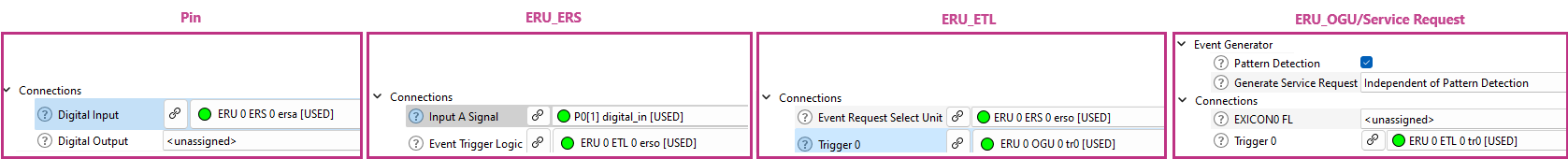
Refer to the ERU Personality section for Interrupt configuration details.
Refer to the API reference General Purpose Input Output (GPIO) for the API details.
Refer to the device Datasheet and Reference Manual for HW details.
The Event Request Unit (ERU) architecture includes three subunits: Event Request Select (ERS), Event Trigger Logic (ETL), and Output Gating Unit (OGU).
Thus, the ERU personality is represented as the three personalities of the ERU subunits.
For more details, refer to:
The ERS personality provides a graphical interface to connect a corresponding ERS input channel to a specific event source, to determine the ERS output signal Combination Logic, and to connect an ERS unit with a corresponding ETL unit.
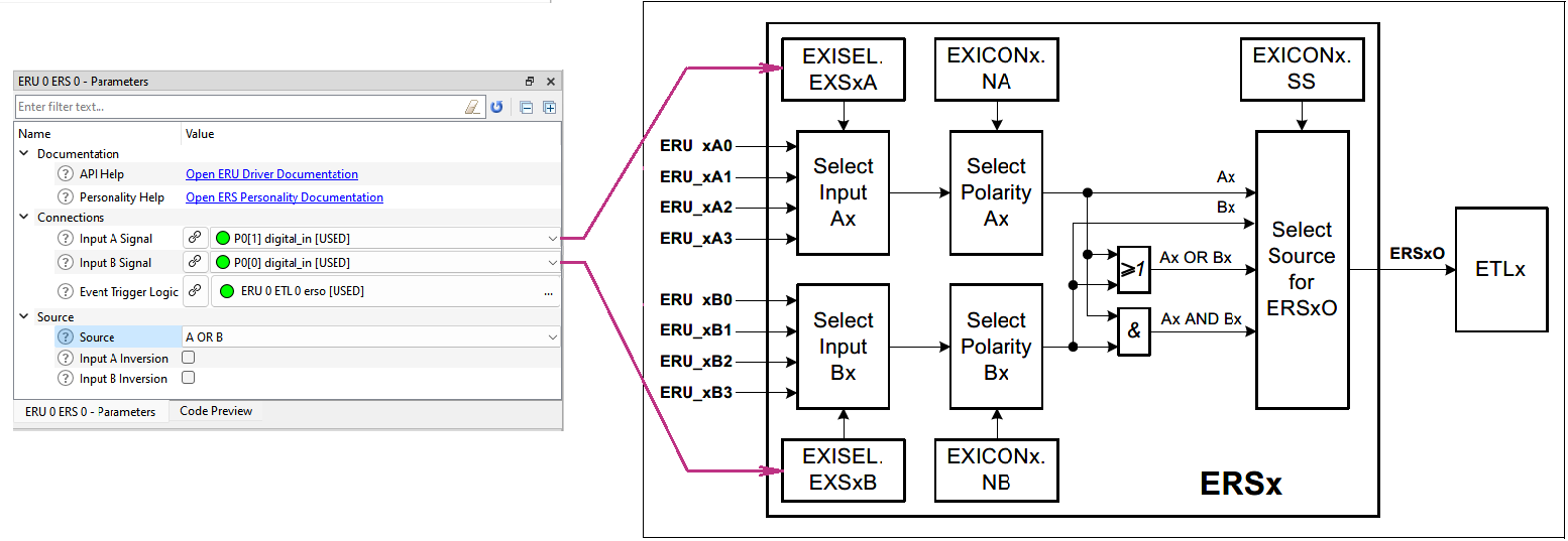
After ERS is set, the next step of the ERU adjustment by the configuration chain is configuration of the ETL.
The ETL personality provides a graphical interface to determine the conditions of incoming signal processing. If the incoming signal satisfies the conditions defined by the "Edge Detection" parameter, the signal is regarded as a true event.
The event generates a trigger, whose distribution path to OGU is also controlled by the parameters of the ETL personality GUI.
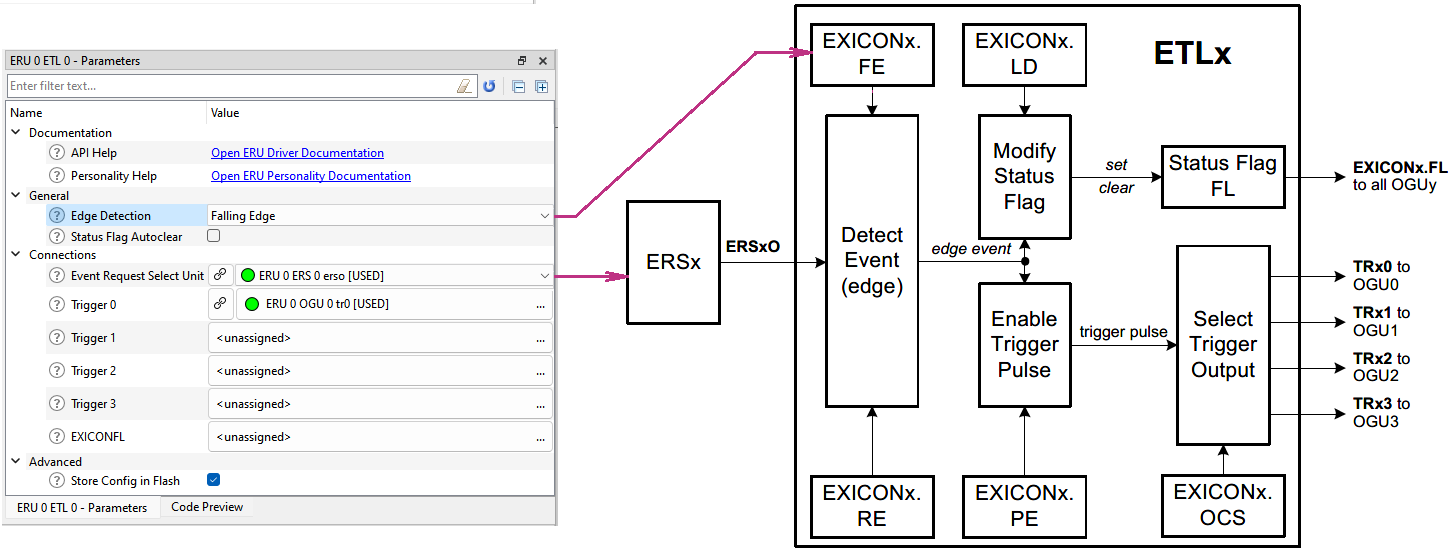
To continue ERU adjustments, go to the OGU personality configuration by the configuration chain.
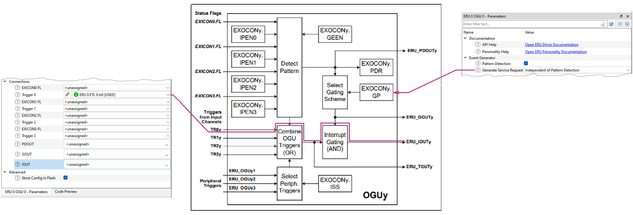
An OGU unit combines trigger events and status information and gates the Output. The OGU personality provides a graphical interface to determine in which way that will occurs.
OGU Outputs may be used as triggers for the other units, for example, to DMA.
An OGU reaction may be setting the service request generation. To enable the service request generation, check the "Pattern Detection" parameter.
Refer to the API reference Event Request Unit (ERU) for the API details.
Refer to the XMC 1000, XMC 4000 Event Request Unit (ERU) Application Note.
Refer to the device Datasheet and Reference Manual for HW details.
The Ethernet MAC (ETH) personality provides a graphical interface to configure the ETH hardware module.
The settings collected in the ETH Personality GUI allow to configure only part of the consumer's Ethernet application - the physical layer (PHY) and data exchange layer, see the picture below.
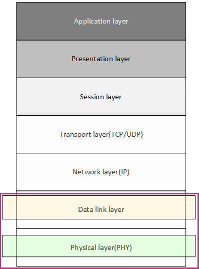
The network and protocol layers, as well as their configuration, must be implemented by the user in their application. The initialization code generated by the ETH personality is a basic template for the user application or for a code example from the manufacturer.
When the ETH Personality connects to a project, an informational message displays in the Notice List pane.
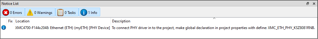
The message reminds the user to make additional settings (global preprocessor #define) for the MTB project after completing the settings in the Device Configurator.
After performing this additional definition, the function call will become available:
XMC_ETH_PHY_Init((XMC_ETH_MAC_t*)&myETH_mac, MyETH_PHY_ADDR, &myETH_phy_config);
The global #define can be made in several ways:
The ETH personality configurations allow the user to configure the usage of one of the three PHY device drivers included in the XMClib or create their own driver for an alternative PHY device.
The interface between the microcontroller and the PHY device may be configured by the personality settings. This may be either an RMII or MII interface. The RMII interface is always available for configuration, but the MII interface is only available for MCUs with more than 100 pins.
After selecting the “Enable Autonegotiation” and/or “Poll Received Data”, messages display in the Notice List pane to inform the user to implement such functionality on their own.

The selection of the "Receive Broadcast Frames" and "Enable Promiscuous Mode" options just adds function calls to the generated code without displaying messages for the user.
__attribute__((aligned(4))) XMC_ETH_MAC_DMA_DESC_t myETH_MTL_rx_desc[myETH_MTL_NUM_RX_BUF] __attribute__((section ("ETH_RAM")));__attribute__((aligned(4))) XMC_ETH_MAC_DMA_DESC_t myETH_MTL_tx_desc[myETH_MTL_NUM_TX_BUF] __attribute__((section ("ETH_RAM")));__attribute__((aligned(4))) uint8_t myETH_MTL_rx_buf[myETH_MTL_NUM_RX_BUF][XMC_ETH_MAC_BUF_SIZE] __attribute__((section ("ETH_RAM")));__attribute__((aligned(4))) uint8_t myETH_MTL_tx_buf[myETH_MTL_NUM_TX_BUF][XMC_ETH_MAC_BUF_SIZE] __attribute__((section ("ETH_RAM")));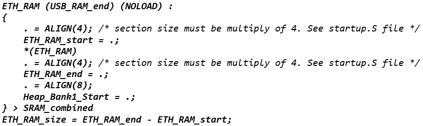
Refer to the API reference Ethernet MAC (ETH_MAC) and Ethernet PHY (ETH_PHY) for the API details.
Refer to the device Datasheet and Reference Manual for HW details.
There are two major revisions: 1.0 and 2.0.
CCU4 1.0 is legacy and contains old-style EVENT_HANDLER definitions, which are deprecated and not recommended for usage in new applications.
CCU4 1.0 is left in XMCLib for the backward compatibility with already created projects not to be updated by the user.
The CCU4 1.0 support will be removed in the next major XMCLib revision.
CCU4 2.0 is almost the same as 1.0 but without the deprecated items, so it is recommended for new applications.
Modern INTERRUPT_HANDLER definitions recommended for usage in applications are generated instead of the deprecated items:

These newly generated definitions can be used in the application code, for example for the xmc4xxx devices:
and for enabling the CCU4 interrupt before starting the block:
Refer to the API reference Capture Compare Unit 4(CCU4) for the API details.
Refer to the device Datasheet and Reference Manual for the HW details.
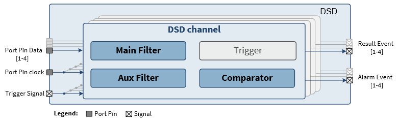
The general DSD block configuration structure:
The single channel GUI configurates a separate DSD channel:
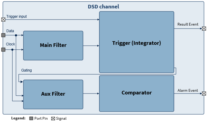
The Trigger (Integrator) settings are available for Advanced Preconfiguration Mode only.
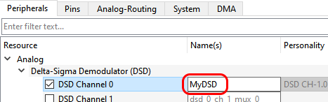
Note that all the public generated code items are prefixed with the name given in the Device Configurator:
The personality generates a base address, channel ID, and interrupt-related macros that can be used in the application code:
and then, for enabling the DSD interrupts and starting the block itself:
Refer to the API reference Delta Sigma Demodulator (DSD) for the API details.
Refer to the device Datasheet and Reference Manual for the HW details.
The personality provides the following functionalities using the CSG peripheral:
The personality provides the following functionalities using the CCU8 and HRC peripherals:
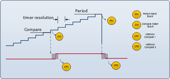
The next figure shows the functional overview of the PWM generation. The period match (PM) value is calculated based on the frequency and the compare match (CM) is calculated based on the duty cycle. The PWM state changes at the period and compare matches.
In this mode, we can use the 2 compare registers to generate 2 pairs of complementary outputs, which means a total of 4 outputs. The minimum duty that can be generated is 0% and the maximum is 100%. Here, the output is initially LOW until a compare match occurs. The output remains HIGH until a next match occurs.
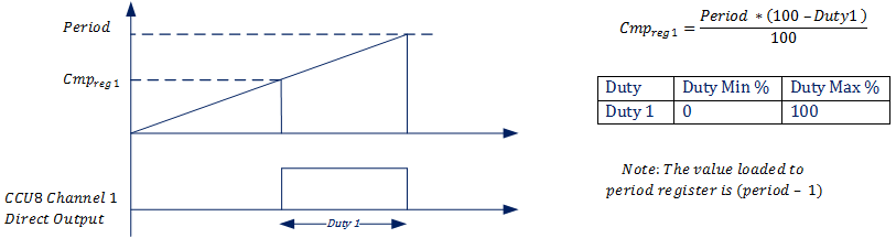
Example with XMC4400:
\( Clock = 120MHz. \)
\( Prescaler = 0. \)
\( Required\:frequency\:of\:operation\:(F) = 100KHz. \)
\( Duty\:required\:(D) = 30\%. \)
\( Period = \frac{Clock}{(1 \texttt{<<} Prescaler) \cdot F} \)
\( Cmp_{reg} = \frac{Period \cdot (100 - D)}{100} \)
\( Period = \frac{120,000,000}{(1 \texttt{<<} 0) \cdot 100,000} \)
\( Period = 1200 \) Note: The value loaded to period register is \( (Period - 1) \), i.e. \( 1199. \)
\( Cmp_{reg} = \frac{1200 \cdot (100 - 30)}{100} \)
\( Cmp_{reg} = 840 \)
In this mode, we can use the 2 compare registers to generate 2 pairs of complementary outputs, which means a total of 4 outputs. The minimum duty that can be generated is 0% and the maximum is 100%. Here, the output is initially LOW. When a compare match occurs during the timer up-counting, the output is set HIGH. The output remains HIGH until a compare match occurs again during the timer down-counting. Here, we can see that the ON time of channel 1 and channel 2 are aligned to the time period center.
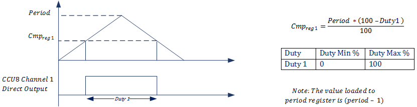
Example with XMC4400:
\( Clock = 120MHz. \)
\( Prescaler = 0. \)
\( Required\:frequency\:of\:operation\:(F) = 100KHz. \)
\( Duty\:required\:(D) = 30\%. \)
\( Period = \frac{Clock}{(1 \texttt{<<} Prescaler) \cdot 2F} \)
\( Cmp_{reg} = \frac{Period \cdot (100 - D)}{100} \)
\( Period = \frac{120,000,000}{(1 \texttt{<<} 0) \cdot 2 \cdot 100,000} \)
\( Period = 600 \) Note: The value loaded to period register is \( (Period - 1) \), i.e. \( 599. \)
\( Cmp_{reg} = \frac{600 \cdot (100 - 30)}{100} \)
\( Cmp_{reg} = 420 \)
In this mode, we can use the 2 compare registers to generate 1 pair of complementary outputs, which means a total of 2 outputs. The minimum duty that can be generated is 0% and the maximum is 100%. Here, the output remains LOW until a channel 1 compare match occurs. This duration can be called "shift". The output remains HIGH until a channel 2 compare match occurs. This duration is determined by the duty. The condition is that the channel 2 register value is required to be greater that the channel 1 register value. This allows us to place the ON time anywhere in the time period, as long as the limiting conditions are met.
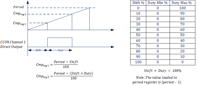
Example with XMC4400:
\( Clock = 120MHz. \)
\( Prescaler = 0. \)
\( Required\:frequency\:of\:operation\:(F) = 100KHz. \)
\( Shift\:required\:(S) = 40\%. \)
\( Duty\:required\:(D) = 30\%. \)
\( Period = \frac{Clock}{(1 \texttt{<<} Prescaler) \cdot F} \)
\( Cmp_{reg1} = \frac{Period \cdot S}{100} \)
\( Cmp_{reg2} = \frac{Period \cdot (S + D)}{100} \)
\( Period = \frac{120,000,000}{(1 \texttt{<<} 0) \cdot 100,000} \)
\( Period = 1200 \) Note: The value loaded to period register is \( (Period - 1) \), i.e. \( 1199. \)
\( Cmp_{reg1} = \frac{1200 \cdot 40}{100} \)
\( Cmp_{reg1} = 480 \)
\( Cmp_{reg2} = \frac{1200 \cdot (40 + 30)}{100} \)
\( Cmp_{reg2} = 840 \)
In this mode, we can use the 2 compare registers to generate 1 pair of complementary outputs, which means a total of 2 outputs. The minimum duty that can be generated is 0% and the maximum is 100%. Here, the output remains LOW until a channel 1 compare match occurs in the timer up-counting. This duration can be called "shift". The output remains HIGH until a channel 2 compare match occurs during the timer down-counting. This duration is determined by the duty.
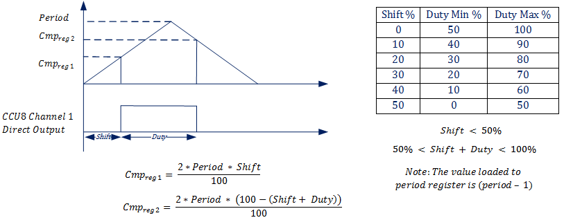
Example with XMC4400:
\( Clock = 120MHz. \)
\( Prescaler = 0. \)
\( Required\:frequency\:of\:operation\:(F) = 100KHz. \)
\( Shift\:required\:(S) = 40\%. \)
\( Duty\:required\:(D) = 40\%. \)
\( Period = \frac{Clock}{(1 \texttt{<<} Prescaler) \cdot 2F} \)
\( Cmp_{reg1} = \frac{2 \cdot Period \cdot S}{100} \)
\( Cmp_{reg2} = \frac{2 \cdot Period \cdot (100 - (S + D))}{100} \)
\( Period = \frac{120,000,000}{(1 \texttt{<<} 0) \cdot 2 \cdot 100,000} \)
\( Period = 600 \) Note: The value loaded to period register is \( (Period - 1) \), i.e. \( 599. \)
\( Cmp_{reg1} = \frac{2 \cdot 600 \cdot 40}{100} \)
\( Cmp_{reg1} = 480 \)
\( Cmp_{reg2} = \frac{2 \cdot 600 \cdot (40 + 40)}{100} \)
\( Cmp_{reg2} = 480 \)
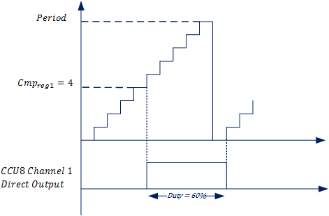
Example with XMC4400:
\( Period = 10. \)
\( Duty\:required\:(D) = 60\%. \)
\( Cmp_{reg} = \frac{Period \cdot (100 - D)}{100} \)
\( Cmp_{reg} = \frac{10 \cdot (100 - 60)}{100} \)
\( Cmp_{reg} = 4 \)
Now let us say:
\( Duty\:required\:(D) = 65\%. \)
\( Cmp_{reg} = \frac{10 \cdot (100 - 65)}{100} = 3.5 ≅ 3 \)
With compare register 3, we get a duty of 70%. Therefore, we are not able to get a duty of 65% with a period of 10. Hence, need to use the HRPWM module.
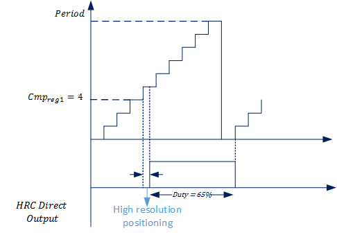
The CCU8 output is fed to the HRPWM module. The HRPWM module has two registers - CR1 and CR2. CR1 delays the rising edge of the output, whereas CR2 extends the falling edge of the output. The High Resolution module has a resolution of 150 Pico second. We can achieve the positioning of the output in the step of 150ps. Thus, by configuring the CR1, CR2 registers we can achieve finer generation of the shift and duty. Refer to the reference manual to determine the minimum and maximum duty cycle feasible with the HRPWM module.
Refer to the API reference High Resolution PWM Unit (HRPWM) for the API details.
Refer to the device Datasheet and Reference Manual for the HW details.
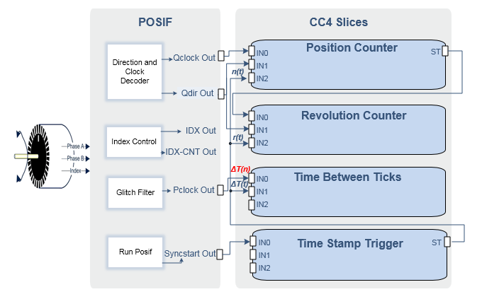
Quadrature Decoder mode is used to find the position and speed of the motor using the incremental encoder. The profile is designed so that it can estimate the angle by consuming 3 CCU4 slices and an optional CCU4 slice along with POSIF and its interconnections.
Four CCU4 slices are consumed for the following purposes:
The POSIF module and its interconnection with CCU4 are depicted in the following diagram:
Hall Sensor mode is used to find the position and speed of the motor using 2 or 3 hall sensors. The POSIF personality in Hall Sensor mode uses two CCU4 slices - one to add a phase delay and one to capture the time between two correct hall patterns.
The personality supports 3 hall sensors and 2 hall sensors in the following use cases:
Refer to the API reference Position Interface Unit (POSIF) for the API details.
Refer to the device Datasheet and Reference Manual for the HW details.
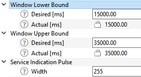
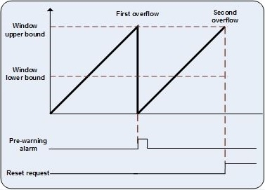
The Window boundaries configuration:
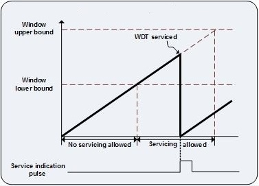
The Pre-Warning Alarm interrupt configuration:
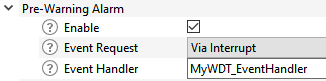
The configurator performs the [name]_EventHandler registration in the generated code, so declare it in the application code, for example for the xmc4xxx devices:
and then start the block itself (the rest of configurations are performed in the generated code):
Refer to the API reference Watchdog driver (WDT) for the API details.
Refer to the device Datasheet and Reference Manual for HW details.