|
XMC Peripheral Library for XMC1000 Family
|
|
XMC Peripheral Library for XMC1000 Family
|
The XMC Peripheral Library includes a set of files to enable the ModusToolbox™ Device Configurator functionality. These files are known as personalities. They describe the GUI to the microcontroller hardware resources for the Device Configurator in the xml format. Each hardware resource of a microcontroller has its own personality.
Based on the user settings, personalities generate initialization code (configuration structures and initialization API calls) executed within the init_cycfg_all() function. The init_cycfg_all() function is usually executed within the cybsp_init() function or may be called directly in the main() function by the user. The system clock personalities generate a strong definition of the SystemCoreClockSetup() function executed at a startup (before jumping to main.c, not within the init_cycfg_all() unlike other ModusToolbox™ PDL products).
For more details, refer to:
The parameters of microcontroller resources are allocated in groups. Most of the personalities have groups named: Documentation, Connections, Advanced.
The "Advanced" group may contain all or one of the listed parameters:
The pins of the Pin personality for XMC family microcontrollers do not generate service requests. This feature is determined by the hardware architecture of the XMC family.
However, pins can be configured as event resources for the Event Request Unit (ERU), and ERU will generate a service request instead of Pin.
To adjust an Interrupt from a pin (GPIO) requires the adjustments by the configurations chain: Pin - ERU_ERS - ERU_ETL - ERU_OGU/Service Request.
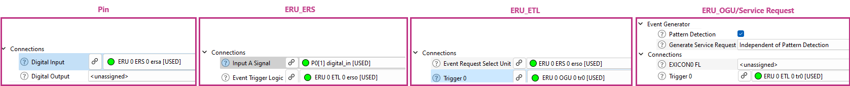
Refer to the ERU Personality section for Interrupt configuration details.
Refer to the API reference General Purpose Input Output (GPIO) for the API details.
Refer to the device Datasheet and Reference Manual for HW details.
The Event Request Unit (ERU) architecture includes three subunits: Event Request Select (ERS), Event Trigger Logic (ETL), and Output Gating Unit (OGU).
Thus, the ERU personality is represented as the three personalities of the ERU subunits.
For more details, refer to:
The ERS personality provides a graphical interface to connect a corresponding ERS input channel to a specific event source, to determine the ERS output signal Combination Logic, and to connect an ERS unit with a corresponding ETL unit.
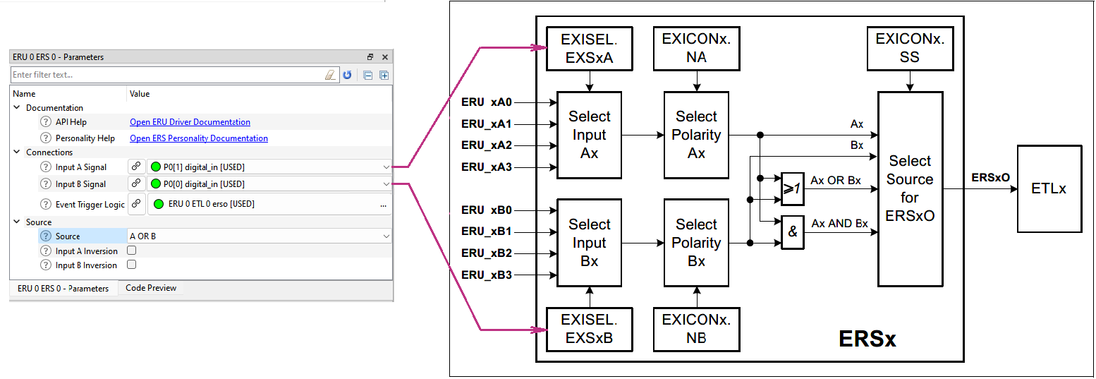
After ERS is set, the next step of the ERU adjustment by the configuration chain is configuration of the ETL.
The ETL personality provides a graphical interface to determine the conditions of incoming signal processing. If the incoming signal satisfies the conditions defined by the "Edge Detection" parameter, the signal is regarded as a true event.
The event generates a trigger, whose distribution path to OGU is also controlled by the parameters of the ETL personality GUI.
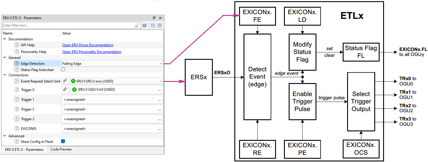
To continue ERU adjustments, go to the OGU personality configuration by the configuration chain.
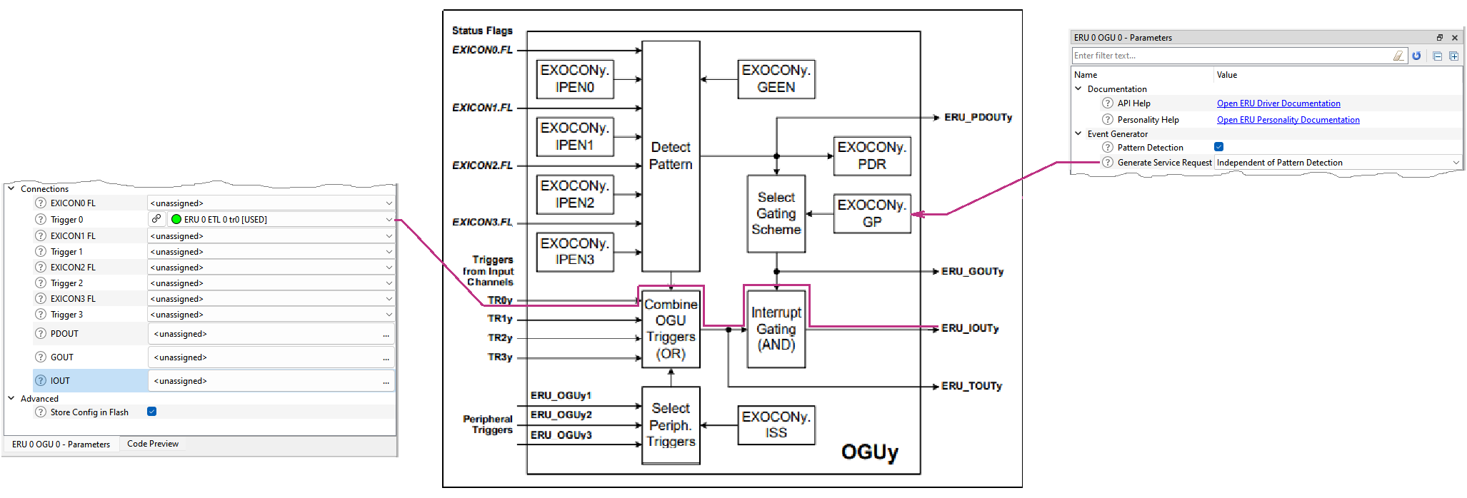
An OGU unit combines trigger events and status information and gates the Output. The OGU personality provides a graphical interface to determine in which way that will occurs.
OGU Outputs may be used as triggers for the other units, for example, to DMA.
An OGU reaction may be setting the service request generation. To enable the service request generation, check the "Pattern Detection" parameter.
Refer to the API reference Event Request Unit (ERU) for the API details.
Refer to the XMC 1000, XMC 4000 Event Request Unit (ERU) Application Note.
Refer to the device Datasheet and Reference Manual for HW details.
There are two major revisions: 1.0 and 2.0.
CCU4 1.0 is legacy and contains old-style EVENT_HANDLER definitions, which are deprecated and not recommended for usage in new applications.
CCU4 1.0 is left in XMCLib for the backward compatibility with already created projects not to be updated by the user.
The CCU4 1.0 support will be removed in the next major XMCLib revision.
CCU4 2.0 is almost the same as 1.0 but without the deprecated items, so it is recommended for new applications.
Modern INTERRUPT_HANDLER definitions recommended for usage in applications are generated instead of the deprecated items:
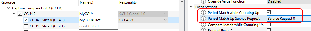

These newly generated definitions can be used in the application code, for example for the xmc4xxx devices:
and for enabling the CCU4 interrupt before starting the block:
Refer to the API reference Capture Compare Unit 4(CCU4) for the API details.
Refer to the device Datasheet and Reference Manual for the HW details.
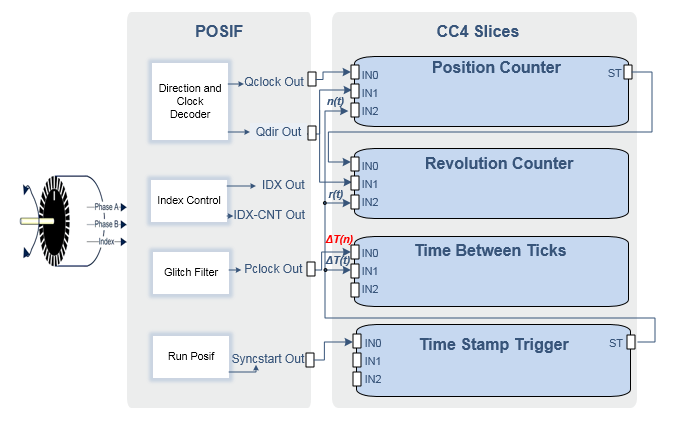
Quadrature Decoder mode is used to find the position and speed of the motor using the incremental encoder. The profile is designed so that it can estimate the angle by consuming 3 CCU4 slices and an optional CCU4 slice along with POSIF and its interconnections.
Four CCU4 slices are consumed for the following purposes:
The POSIF module and its interconnection with CCU4 are depicted in the following diagram:
Hall Sensor mode is used to find the position and speed of the motor using 2 or 3 hall sensors. The POSIF personality in Hall Sensor mode uses two CCU4 slices - one to add a phase delay and one to capture the time between two correct hall patterns.
The personality supports 3 hall sensors and 2 hall sensors in the following use cases:
Refer to the API reference Position Interface Unit (POSIF) for the API details.
Refer to the device Datasheet and Reference Manual for the HW details.
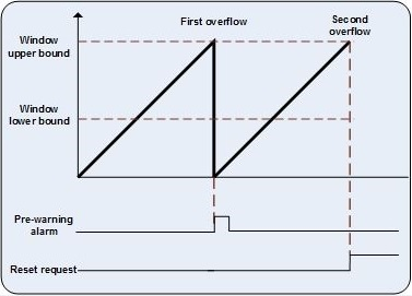
The Window boundaries configuration:
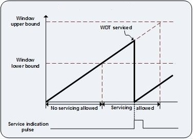
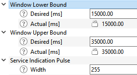
The Pre-Warning Alarm interrupt configuration:
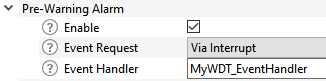
The configurator performs the [name]_EventHandler registration in the generated code, so declare it in the application code, for example for the xmc4xxx devices:
and then start the block itself (the rest of configurations are performed in the generated code):
Refer to the API reference Watchdog driver (WDT) for the API details.
Refer to the device Datasheet and Reference Manual for HW details.
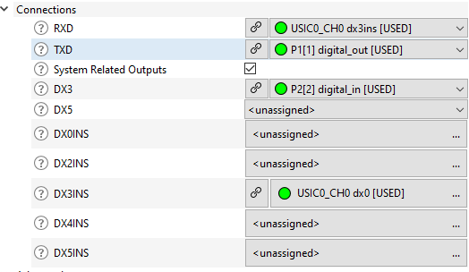
There is a possibility to extend the set of pins available as UART RXD input using pins from DX3 and DX5 input stages. By selecting DX3INS connection for RXD signal, the pin configured on DX3 input is used as RXD, for example:
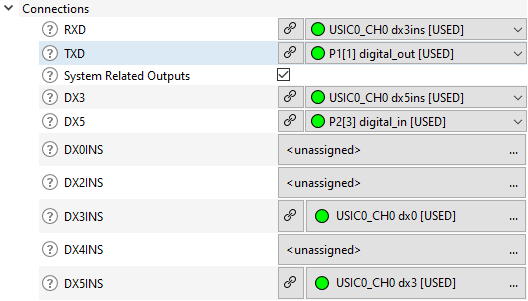
Additionally, the pin set for RXD connection could be extended further with DX5 inputs, if DX5INS connection is selected for DX3 input in the previous example:
Refer to the API reference Universal Asynchronous Receiver/Transmitter (UART) for the API details.
Refer to the device Datasheet and Reference Manual for HW details.