 |
MTB CAT1 Peripheral driver library
|
|
MTB CAT1 Peripheral driver library
|
The inter-processor communication (IPC) driver provides a safe and reliable method to transfer data between CPUs.
Hardware locking ensures that only one device can acquire and transfer data at a time so no data is lost or overwritten by asynchronous processes or CPUs.
Include either cy_ipc_pipe.h, cy_ipc_sema.h or cy_ipc_bt.h. Alternatively include cy_pdl.h to get access to all functions and declarations in the PDL.
There are four parts to the API:
Firmware does not need to use the DRV API. It can implement IPC functionality entirely with the PIPE, SEMA and BTSS APIs.
IPC is implemented in hardware as a collection of individual communication channels, each with a set of 32-bit registers. The IPC design implements a set of interrupts that enable each processor to notify the other that data is available, or has been processed. There is also a locking mechanism that allows only one CPU to gain access at a time.
In case of devices having multiple IPC IP instances, IPC channels and IPC interrupts are associated with each other within particular IP instance. It is not possible to create an IPC mechanism where IPC channels of one IPC instance interacts with interrupts of another IPC instance. Following table describes channels and interrupts present in different devices:
| Device category | IPC IP instances | Channel numbers | Interrupt numbers |
|---|---|---|---|
| CAT1A | IPC0 ( Single instance ) | 0-15 | 0-15 |
| CAT1B | IPC0 ( Single instance ) | 0-3 | 0-1 |
| CAT1C | IPC0 ( Single instance ) | 0-7 | 0-7 |
| CAT1D | IPC0 ( First instance ) | 0-15 | 0-7 |
| IPC1 ( Second instance ) | 16-31 | 8-15 |
The Driver-level API manages each channel's registers to implement IPC functionality. For information on the IPC registers, see the IPC chapter of the Technical Reference Manual (TRM).
At the hardware level, communication is a five-step process.
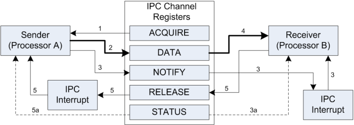
These transactions are handled transparently by the DRV-level API. Use the PIPE, SEMA and BTSS layers of the API to implement communication in your application. The data transferred is limited to a single 32-bit value in case of PIPE and SEMA and two 32-bit value incase of BTIPC. As implemented by the PIPE API, that value is a pointer to a data structure of arbitrary size and complexity. BTSS uses both 32-bit registers for communication of short messages. If the payload is greater than 7 bytes, then it copies the data to the shared memory between MCU and the BT SS.
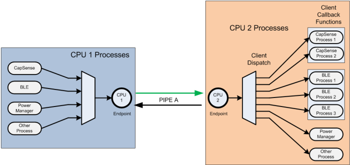
The Pipe is the key element in the PDL design. A pipe is typically a full-duplex communication channel between CPU cores. A pipe allows a single conduit to transfer messages or data to and from multiple processes or CPUs.
A pipe has two endpoints, one on each core. Each endpoint contains a dedicated IPC channel and an interrupt. IPC channels 0-7(8 for the CYB064XX devices) and IPC interrupts 0-7 are reserved for system use.
The pipe also contains the number of clients it supports, and for each client a callback function. So, the pipe can service a number of clients, each with a separate callback function, on either endpoint. The number of clients a pipe supports is the sum of each endpoint's clients.
This design enables any number of processes on the sending core to put arbitrary data into a single pipe. The first element of that data is the client ID of the client that should handle the data.
An interrupt notifies the receiving core that data is available. The receiving core parses the data to identify the client, and then dispatches the event to the appropriate client via the client callback function. An interrupt notifies the sending core that the receiver is finished. In this way a single pipe can manage arbitrary data transfers between cores with data flowing in either direction.
The application can use semaphores to control access to shared resources, as required by the application's logic.
The PDL provides specific files that set up default IPC functionality. They are system_psoc6.h, system_psoc6_cm0plus.c and system_psoc6_cm4.c. You can modify these files based on the requirements of your design. If you use PSoC Creator as a development environment, it will not overwrite your changes when you generate the application or build your code.
BTSS provides dedicated communication channels for communication between MCU and the BT SS. APIs provided handle exchange of Host Controller Interface (HCI) and High Priority Controller (HPC) packets using 4 dedicated IPC channels. Two dedicated Up Link (UL) channels, one for HCI and another for HPC from MCU to BT SS and two dedicated Down Link (DL) channels, one for HCI and another for HPC from BT SS to MCU are used.
A pipe is a communication channel between two endpoints. PSoC 6 devices support 16 IPC channels, and 16 IPC interrupts, each numbered 0-15. IPC Channels 0-7 and IPC interrupts 0-7 are reserved for system use. Channels 8-15 and interrupts 8-15 are available for application use.
A full duplex pipe uses two IPC channels, one per endpoint. Each endpoint specifies all the information required to process a message (either sent or received). Each endpoint is configured to use an IPC channel, and an IPC interrupt. Common practice is to use the interrupt with the same number as the IPC channel. However, IPC Interrupts are not directly associated with the IPC channels, so any channel can use any interrupt. Any IPC channel can trigger 0, 1 or all the IPC interrupts at once, depending on the Notify or Release masks used.
It is also possible to set up a one-directional pipe, using a single IPC channel. In this design one processor is always the sender, and the other is always the receiver. However, there are still two endpoints.
A pipe supports an arbitrary number of clients with an array of callback functions, one per client. The client ID is the index number into the array for the client. After a pipe is configured and initialized, the application calls Cy_IPC_Pipe_RegisterCallback() once per client to register each client's callback function. Multiple clients can use the same callback function. The endpoints in a pipe share the callback array.
Use Cy_IPC_Pipe_SendMessage() to send data. You specify both the "to" and "from" endpoints, and a callback function to be used when the data transfer is complete. The data is a 32-bit void pointer. The data pointed to is arbitrary, and can be an array, a structure, or a location in memory. The only limitation is that the first element of the data must be a 32-bit unsigned word containing a client ID number. The ID number is the index into the callback array.
When a message is sent, the receiving endpoint's interrupt handler is called. The ISR can perform any task required by the design. However, as part of its function it calls Cy_IPC_Pipe_ExecCallback. This function retrieves the client ID from the data and calls the associated callback function. The user-supplied callback function handles the data in whatever way is appropriate based on the application logic.
After the callback function is returned by the receiver, it invokes the release callback function defined by the sender of the message.
A semaphore is a flag the application uses to control access to a shared resource. The SEMA-level API uses an IPC channel to implement semaphores. Startup code sets up a default semaphore system. The default system creates an array of 128 semaphores (four 32-bit values). Semaphores 0-15 are reserved for system use. See Configuration Considerations - SEMA.
Functions are available to initialize the semaphore system, to set or clear a semaphore, or to get the semaphore's current status. Application logic uses SEMA functions to relate a particular semaphore to a particular shared resource, and set, clear, or check the flag when accessing the shared resource.
A Bluetooth Sub-system (BTSS) layer is a communication channel between the MCU and the BT Sub-system. It uses 4 IPC channels and 2 interrupts. 2 UL channels (one for HCI and HPC each) and 2 DL channels (one for HCI and HPC each). IPC interrupt 0 is used to interrupt the BT SS and IPC interrupt 1 is used to interrupt the MCU. IPC channels 0 is used for HCI UL, channel 1 is used from HCI DL, IPC channels 2 is used for HPC UL, and channel 3 is used from HPC DL. The IPC interrupt gets triggered for both Notify and Release channel. Bluetooth stack interface layer registers a callback function for notification when BT SS sends an HCI packet. It also provides APIs to read the HCI packets from the BT SS. On the UL path, it supports APIs to send HCI packet from MCU to BT SS.
The communication is made more efficient by eliminating the need for buffers by packing them into the DATA0 and DATA1 IPC channel registers when payload length is less than or equal to 7 bytes. In case the where the payload length is greater than 7 bytes, it would use the shared memory to send/receive the packet.
This layer support control message communication between the MCU and the BT SS using the HPC channels. The HPC channel is used for power management, IO configuration, access for TRNG, etc. APIs are provided to send HPC packets to the BT SS. It also supports APIs to register the callback function to get notification on receiving the HPC packets from the BT SS. Multiple modules running on the MCU can register callback functions. Maximum number of HPC callbacks supported is decided by the MAX_BT_IPC_HPC_CB macro. All the shared buffer management mechanism is built into this layer.
There are none. The startup files set up the required CYPIPE for system use. Do not modify the CYPIPE. It uses IPC channels 5 and 6 to implement full duplex communication between cores. See System Interrupt (SysInt) for background.
To create your own pipe (USRPIPE) you should edit startup files and take 4 steps:
Startup code calls Cy_IPC_Sema_Init() with default values to set up semaphore functionality. By default, the semaphore system uses IPC channel 4, and creates 128 semaphores. Do not change the IPC channel. You can change the number of semaphores.
To change the number of semaphores, modify this line of code in system_psoc6.h.
Startup also declares array ipcSemaArray to hold the semaphore flags based on the size defined for this symbol. Use increments of 32. You must have at least 32 semaphores. Semaphores 0-15 are reserved for system use. Your application can use semaphores greater than 15.
Application code calls Cy_BTIPC_Init() with configuration parameters to set up BTSS IPC functionality. By default, the BT IPC uses IPC channel 0,1,2 and 3. Do not change the IPC channel.
To change the number of callbacks supported, modify this line of code in cy_ipc_bt.h.
To change the count of maximum number of buffers shared by BT SS, modify this line of code in cy_ipc_bt.h.
If the default startup file is not used, or SystemInit() is not called in your project, call the following three functions prior to executing any flash or EmEEPROM write or erase operation:
See the technical reference manual(TRM) for more information on the IPC.
| Version | Changes | Reason for Change |
|---|---|---|
| 1.160.1 | Updated driver documentation text. | Documentation update. |
| 1.160 | Added CPUSS_VER2 CM7_2 and CM7_3 support. | Code enhancement. |
| 1.150 | Added support for alternative interrupt mapping. | Code enhancement. |
| 1.140 | Updated condition to handle devices with Data Cache. | Code enhancement. |
| 1.130 | Updated APIs Cy_IPC_Pipe_Init. | Improving interrupt configuration logic. |
| 1.120 | Updated APIs Cy_IPC_Sema_Set, Cy_IPC_Sema_Clear, Cy_IPC_Sema_Status, Cy_IPC_Sema_GetMaxSems.
| Support added for HPC buffer remove command and BT IPC driver enhancements. |
| 1.110 | Updated internal APIs . | Hold PDCM lock at IPC write and to unlock only after CH release by BTSS. |
| 1.100 | Added support for TRAVEO™ II Body Entry devices. Added support for CM0 and CM4 core devices in cy_ipc_pipe API. Replaced some hardcoded values (register size) with the relevant device defines. | Code enhancement and support for new devices. |
| 1.91 | Updated Cy_IPC_Sema_Set, Cy_IPC_Sema_Clear, Cy_IPC_Sema_Status, Cy_IPC_Sema_GetMaxSems APIs Added new macros | Support for CAT1D devices added. |
| 1.90 | Added structure cy_stc_ipc_msg_inrush_mode_t and enum cy_en_btipc_inrush_mode_t, Modified enums cy_en_btipc_lpo_cmd_t and cy_en_btipc_hpcpti_t. | Support for inrush mode selection for CAT1B. |
| Added structure cy_stc_ipc_pipe_ep_config_mask_t and Cy_IPC_Pipe_EndpointInitExt API. | Support for multiple instance of IPC IPs for CAT1D. | |
| 1.80 |
|
|
| 1.70 | Added BT IPC service layer. | To support communication between MCU and BTSS through IPC. |
| 1.60 | Added new APIs to use DATA0 and DATA1 for short messages. | Enhancement based on usability/efficiency. |
| 1.50 | Updated attribute usage for the linker section placement. | Enhancement based on usability feedback. |
| Fixed MISRA 2012 violations. | MISRA 2012 compliance. | |
| 1.40.2 | Updated information about IPC resources reserved for the system usage in PIPE layer section. | Documentation enhancement. |
| 1.40.1 | Minor documentation updates. | Documentation enhancement. |
| 1.40 | Moved cy_semaData structure to the RAM section called ".cy_sharedmem". | Support Secure Boot devices. |
| 1.30 | Flattened the organization of the driver source code into the single source directory and the single include directory. | Driver library directory-structure simplification. |
| Moved the Cy_IPC_SystemSemaInit(), Cy_IPC_SystemPipeInit() functions implementation from IPC to Startup, removed cy_ipc_config.c and cy_ipc_config.h files. | Changed IPC driver configuration method from compile time to run time. | |
| Added register access layer. Use register access macros instead of direct register access using dereferenced pointers. | Makes register access device-independent, so that the PDL does not need to be recompiled for each supported part number. | |
| 1.20 | Added Cy_IPC_Pipe_ExecuteCallback function. Updated documentation about user pipe initialization. | Interface improvement, documentation update |
| 1.10.1 | Updated description of the Cy_IPC_Pipe_Init, Cy_IPC_Pipe_EndpointInit, Cy_IPC_Sema_Set functions. Added / updated code snippets. | Documentation update and clarification |
| 1.10 | Added support for more IPC structures | New device support |
| 1.0 | Initial version |
API Reference | |
| IPC driver layer (IPC_DRV) | |
| The functions of this layer are used in the higher IPC levels (Semaphores and Pipes). | |
| IPC semaphores layer (IPC_SEMA) | |
| The semaphores layer functions made use of a single IPC channel to allow multiple semaphores that can be used by system or user function calls. | |
| IPC pipes layer (IPC_PIPE) | |
| The Pipe functions provide a method to transfer one or more words of data between CPUs or tasks. | |
| IPC Bluetooth sub-system layer (IPC_BTSS) | |
| All the HCI APIs are intended to be called by the stack interface layer, and not meant to be called by the application developers. | |