The CAN FD driver provides an easy method to access the CAN FD IP block registers and provides simple functionality for sending and receiving data between devices in the CAN FD network.
The CAN FD driver provides an API to configure the main features - mode, bit time, message buffers - and transmit and receive message in all modes:
- Classic CAN using 11-bit identifiers
- Classic CAN using 29-bit identifiers
- CAN Flexible Data using 11-bit identifiers
- CAN Flexible Data using 29-bit identifiers.
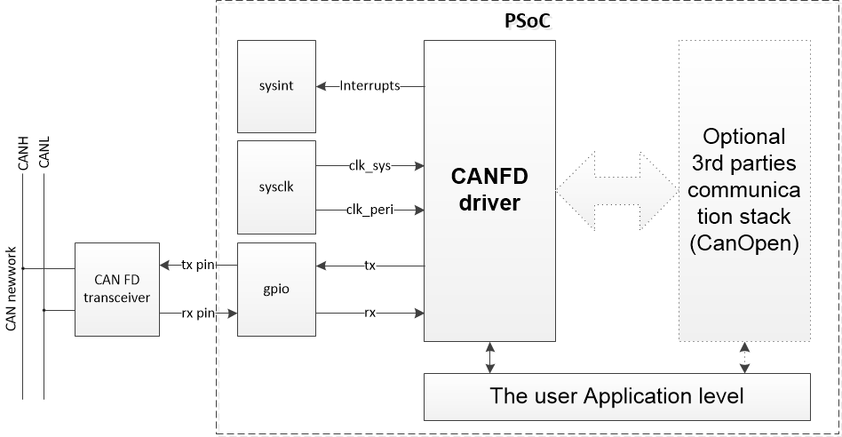
CAN FD Solution
Configuration Considerations
Specification of the sample code is as follows:
- Selectable CAN FD mode or CAN mode
- Configurable CAN clock
- Configurable CAN Bit rate
- Configurable CAN FD Bit rate
- Configurable Standard ID filter
- Configurable Extended Message ID Filter
- Tx-Rx Element Size : 8 bytes (CAN mode)
- Tx-Rx Element Size : 64 bytes (CAN FD mode)
- Rx FIFO configuration
- Interrupts :
CY_CANFD_RX_FIFO_0_NEW_MESSAGE (Message stored to Rx FIFO 0)
CY_CANFD_RX_FIFO_1_NEW_MESSAGE (Message stored to Rx FIFO 1)
CY_CANFD_RX_BUFFER_NEW_MESSAGE (Message stored to Dedicated Rx Buffer).
Sends data of ID:0x200 periodically in the main(). Echobacks received data by incrementing the ID of the received packet in the receiving interrupt.(CanFDIrqHandler() — CanFDCallbackRx())
Use ModusToolbox Device Configurator Tool to generate initialization code
The steps to generate initialization code using the ModusToolbox Device Configurator Tool:
- Launch the ModusToolbox Device Configurator Tool.
- Switch to the Peripherals tab. Enable the CAN FD channel personality under Communication and enter Alias (default is canfd_0_chan_0).
- Go to the Parameters Pane for the CAN FD Personality and configure it with the desired parameters (set the Clock Signal divider, set the bit timing configuration, set the other parameters per Configuration Considerations, etc).
- Perform File->Save for the initialization code to generate.
Now, all required CAN FD initialization code and configuration prerequisites will be generated:
- The Peripheral Clock Divider assignment and analog routing are parts of the init_cycfg_all() routine. Place the call of the init_cycfg_all() function before using any CAN FD API functions to ensure initialization of all external resources required for the CAN FD operation.
- The CAN FD configuration structure declaration is in the cycfg_peripherals.h file and its initialization is in the cycfg_peripherals.c file. The variable name is <CAN_FD_Alias_Name>_config (default is canfd_0_chan_0_config). It must be used with Cy_CANFD_Init() function.
- TX buffers structures are initialized. Use these structures to send data.
For the CAN FD interrupt service routine, Cy_CANFD_IrqHandler() can be used. It handles reading data from the dedicated RX buffers and RX FIFO buffers. Corresponding callback functions are called for error interrupts, RX interrupts and TX complete interrupt. Put the names of callback functions to the Callback functions parameters section. Put NULL if no callback function to be used.
- Note
- Only RX interrupt sources are enabled by default. Use Cy_CANFD_SetInterruptMask() to enable other interrupt sources.
-
Interrupt flags are set regardless of the interrupt enable register. Cy_CANFD_IrqHandler will check and process all supported interrupts when triggered with any enabled interrupt source.
void CanfdInterruptHandler(void)
{
}
void Cy_CANFD_IrqHandler(CANFD_Type *base, uint32_t chan, cy_stc_canfd_context_t const *context)
CAN FD (Status/Error/Rx/Tx) interrupt ISR.
Definition: cy_canfd.c:1477
Set up the interrupt handler to be called with CAN FD events. The CAN FD block has two interrupt lines which can be assigned to different interrupt sources using Cy_CANFD_SetInterruptLine(): canfd_0_interrupts0_0_IRQn and canfd_0_interrupts1_0_IRQn. Also, the CAN FD block has a consolidated interrupt canfd_0_interrupt0_IRQn. The following code shows how to set up the interrupt handler.
{
{
canfd_0_interrupts0_0_IRQn,
3UL
};
NVIC_EnableIRQ(canfd_0_interrupts0_0_IRQn);
}
Initialization configuration structure for a single interrupt channel.
Definition: cy_sysint.h:227
cy_en_sysint_status_t Cy_SysInt_Init(const cy_stc_sysint_t *config, cy_israddress userIsr)
Initializes the referenced interrupt by setting the priority and the interrupt vector.
Definition: cy_sysint_v2.c:80
Implement the initialization code manually
Call Cy_CANFD_Init() to initialize the CAN FD module. It initializes the CAN FD module with the configuration parameters, passed in the cy_stc_canfd_config_t structure. It consists of several elements to be defined first.
{
NULL,
CAN_RxMsgCallback,
NULL,
true,
&bitrateConfig,
&fastBitrateConfig,
&tdcConfig,
&sidFiltersConfig,
&extidFiltersConfig,
&globalFilterConfig,
&rxFifo0Config,
&rxFifo1Config,
0x4u,
0x2u,
CY_CAN0MRAM_BASE,
4096u
};
CAN FD configuration.
Definition: cy_canfd.h:968
@ CY_CANFD_BUFFER_DATA_SIZE_64
64 byte data field
Definition: cy_canfd.h:452
The Cy_CANFD_Init() function also initializes the shared context structure used later with other API functions.
Context structure.
Definition: cy_canfd.h:1015
Although the callback functions are optional, they are recommended for use, otherwise, there is no report to the API about any error and transmission or reception events. The example callback function sends received data back to the bus, incrementing ID by 1:
void CAN_RxMsgCallback(bool bRxFifoMsg, uint8_t u8MsgBufOrRxFifoNum,
{
{
{
};
{
true,
false,
0UL
};
{
&t0registerMsg0,
&t1registerMsg0,
};
}
(void)bRxFifoMsg;
(void)u8MsgBufOrRxFifoNum;
}
uint32_t * data_area_f
Rx buffer element for Rn.
Definition: cy_canfd.h:790
cy_stc_canfd_r0_t * r0_f
Rx buffer element for R0.
Definition: cy_canfd.h:788
volatile cy_en_canfd_rtr_t rtr
Remote transmission request.
Definition: cy_canfd.h:769
volatile uint32_t id
Identifier.
Definition: cy_canfd.h:768
cy_stc_canfd_r1_t * r1_f
Rx buffer element for R1.
Definition: cy_canfd.h:789
volatile uint32_t dlc
Data length code.
Definition: cy_canfd.h:778
volatile cy_en_canfd_xtd_t xtd
Extended identifier.
Definition: cy_canfd.h:770
Rx buffer.
Definition: cy_canfd.h:787
T0 register.
Definition: cy_canfd.h:795
T1 register.
Definition: cy_canfd.h:806
Tx buffer register.
Definition: cy_canfd.h:816
@ CY_CANFD_ESI_ERROR_ACTIVE
The transmitting node is error active.
Definition: cy_canfd.h:525
@ CY_CANFD_FDF_CAN_FD_FRAME
The CAN FD frame format (new DLC-coding and CRC)
Definition: cy_canfd.h:533
@ CY_CANFD_FDF_STANDARD_FRAME
The standard frame format.
Definition: cy_canfd.h:532
@ CY_CANFD_RTR_DATA_FRAME
The received frame is a data frame.
Definition: cy_canfd.h:511
cy_en_canfd_status_t Cy_CANFD_UpdateAndTransmitMsgBuffer(CANFD_Type *base, uint32_t chan, const cy_stc_canfd_tx_buffer_t *txBuffer, uint8_t index, cy_stc_canfd_context_t const *context)
Updates the T0 and T1 Tx buffer element parameters in Message RAM and copies data from cy_stc_canfd_t...
Definition: cy_canfd.c:1875
CAN FD IP block requires the configuration of a peripheral clock divider. The following code configures an 8-bit clock divider. The default peripheral clock frequency is 72 MHz. The desired divider value minus one must be passed.
#define DIVIDER_INDEX 0u
#define DIVIDER_VALUE (9u - 1u)
@ CY_SYSCLK_DIV_8_BIT
Divider Type is an 8 bit divider.
Definition: cy_sysclk.h:3336
cy_en_sysclk_status_t Cy_SysClk_PeriphEnableDivider(cy_en_divider_types_t dividerType, uint32_t dividerNum)
Enables the selected divider.
Definition: cy_sysclk_v2.c:2382
cy_en_sysclk_status_t Cy_SysClk_PeriphAssignDivider(en_clk_dst_t ipBlock, cy_en_divider_types_t dividerType, uint32_t dividerNum)
Assigns a programmable divider to a selected IP block, such as a TCPWM or SCB.
Definition: cy_sysclk_v2.c:2368
cy_en_sysclk_status_t Cy_SysClk_PeriphSetDivider(cy_en_divider_types_t dividerType, uint32_t dividerNum, uint32_t dividerValue)
Sets one of the programmable clock dividers.
Definition: cy_sysclk_v2.c:2335
The CAN FD block uses the Port 5 pins for receive (P5[0]) and transmit (P5[1]).
- Connect the specified High-Speed Input Output Multiplexer (HSIOM) selection to the pin.
- Set the pins drive mode for RX and TX.
#define CANFD_PORT (P16_0_PORT)
#define CANFD_RX_NUM (P16_0_NUM)
#define CANFD_TX_NUM (P16_1_NUM)
#define CY_GPIO_DM_STRONG
Strong Drive.
Definition: cy_gpio.h:522
#define CY_GPIO_DM_HIGHZ
Digital High-Z.
Definition: cy_gpio.h:516
__STATIC_INLINE void Cy_GPIO_SetDrivemode(GPIO_PRT_Type *base, uint32_t pinNum, uint32_t value)
Configures the pin output buffer drive mode and input buffer enable.
Definition: cy_gpio.h:1325
__STATIC_INLINE void Cy_GPIO_SetHSIOM(GPIO_PRT_Type *base, uint32_t pinNum, en_hsiom_sel_t value)
Configures the HSIOM connection to the pin.
Definition: cy_gpio.h:926
For the CANFD interrupt service routine, the Cy_CANFD_IrqHandler() can be used. It handles reading data from dedicated RX buffers and RX FIFO buffers. Corresponding callback functions are called for error interrupts, RX interrupts and TX complete interrupt.
- Note
- Only RX interrupt sources are enabled by default. Use Cy_CANFD_SetInterruptMask() to enable other interrupt sources.
-
Interrupt flags are set regardless of the interrupt enable register. Cy_CANFD_IrqHandler will check and process all supported interrupts when triggered with any enabled interrupt source.
void CanfdInterruptHandler(void)
{
}
Setup the interrupt handler to be called with the CAN FD events. The CAN FD block has two interrupt lines, which can be assigned to different interrupt sources using Cy_CANFD_SetInterruptLine(): canfd_0_interrupts0_0_IRQn and canfd_0_interrupts1_0_IRQn. Also, the CAN FD block has a consolidated interrupt canfd_0_interrupt0_IRQn. The following code shows how to set up the interrupt handler.
{
{
canfd_0_interrupts0_0_IRQn,
3UL
};
NVIC_EnableIRQ(canfd_0_interrupts0_0_IRQn);
}
CAN FD has two bit rate settings, for arbitration and data phases. Both are configured with the same structure, containing a pre-scaler, time segment 1, time segment 2 and synchronization jump width.
- Note
- The actual interpretation by the hardware of configured values is one more value than programmed.
-
The bit rate configured for the CAN FD data phase must be higher or equal to the bit rate configured for the arbitration phase.
The CAN time quantum (tq) may be programmed in the range of 1 to 32 CAN FD clock periods: tq = (prescaler + 1) mtq, where mtq is CAN FD block's clock period. The length of the bit time is (programmed values) [timeSegment1 + timeSegment2 + 3] tq.
The example below shows the configuration with the 100 kbps arbitration bit rate and 200 kbps data bit rate. This assumes the peripheral clock frequency of 72 MHz divided by 9 to obtain the 8 MHz clock for the CAN FD block.
{
10u - 1u,
5u - 1u,
2u - 1u,
2u - 1u
};
{
5u - 1u,
5u - 1u,
2u - 1u,
2u - 1u
};
{
false,
0,
0
};
CAN FD bitrate.
Definition: cy_canfd.h:854
CAN FD transceiver delay compensation offset configuration.
Definition: cy_canfd.h:863
CAN FD driver provides API to setup Message ID filtering. There are standard ID and extended ID filters. The desired count of the filters of each type is specified in the cy_stc_canfd_config_t structure and is set once during block initialization. It is possible to change the configured filters settings with Cy_CANFD_SidFilterSetup() and Cy_CANFD_XidFilterSetup(). Use the cy_stc_id_filter_t structure to set up one standard ID filter:
#define MESSAGE_ID0 (0x00000001UL)
#define MESSAGE_ID1 (0x00000010UL)
#define MESSAGE_ID2 (0x00000020UL)
#define MESSAGE_ID3 (0x00010010UL)
#define RX_BUFFER_ELEMENT_1 (0x0UL)
#define RX_BUFFER_ELEMENT_2 (0x1UL)
#define RX_BUFFER_ELEMENT_3 (0x2UL)
#define RX_BUFFER_ELEMENT_4 (0x3UL)
{
{
RX_BUFFER_ELEMENT_1,
MESSAGE_ID0,
},
{
RX_BUFFER_ELEMENT_2,
MESSAGE_ID1,
}
};
{
sizeof(stdIdFilters) / sizeof(stdIdFilters[0]),
stdIdFilters,
};
Standard ID filter configuration.
Definition: cy_canfd.h:871
Message ID filter register.
Definition: cy_canfd.h:824
@ CY_CANFD_SFT_CLASSIC_FILTER
The Classic filter: SFID1 = filter, SFID2 = mask.
Definition: cy_canfd.h:563
@ CY_CANFD_SFEC_STORE_RX_BUFFER
Store into Rx Buffer or as debug message, configuration of SFT[1:0] ignored.
Definition: cy_canfd.h:553
Use the cy_stc_extid_filter_t structure to set up an extended ID filter:
{
MESSAGE_ID2,
};
{
RX_BUFFER_ELEMENT_3,
};
{
MESSAGE_ID3,
};
{
RX_BUFFER_ELEMENT_4,
};
{
{
&filter0F0Config,
&filter0F1Config
},
{
&filter1F0Config,
&filter1F1Config
}
};
{
sizeof(extIdFilters) / sizeof(extIdFilters[0]),
extIdFilters,
0x1fffffffUL
};
Extended ID filter configuration.
Definition: cy_canfd.h:878
F0 register.
Definition: cy_canfd.h:833
F1 register.
Definition: cy_canfd.h:840
Extended message ID filter register.
Definition: cy_canfd.h:847
@ CY_CANFD_EFEC_STORE_RX_BUFFER
Store into Rx Buffer or as debug message, configuration of EFT[1:0] ignored.
Definition: cy_canfd.h:577
@ CY_CANFD_EFEC_DISABLE
Disable the filter element.
Definition: cy_canfd.h:570
@ CY_CANFD_EFT_CLASSIC_FILTER
The Classic filter: EFID1 = filter, EFID2 = mask.
Definition: cy_canfd.h:587
Message IDs that do not match any filter are received according to the global filter set up. The global filter can be set up to receive messages with standard and extended IDs to different FIFO buffers. It can be configured to reject remote frames, as shown below.
{
true,
true
};
Global filter configuration.
Definition: cy_canfd.h:886
@ CY_CANFD_ACCEPT_IN_RXFIFO_0
Accept in Rx FIFO 0.
Definition: cy_canfd.h:465
@ CY_CANFD_ACCEPT_IN_RXFIFO_1
Accept in Rx FIFO 1.
Definition: cy_canfd.h:466
The RX FIFO buffers, FIFO 0 and FIFO 1 are configured once on block initialization using cy_en_canfd_fifo_config_t structure.
{
0u,
1u,
false
};
{
0u,
1u,
false
};
Rx FIFO configuration.
Definition: cy_canfd.h:895
@ CY_CANFD_FIFO_MODE_BLOCKING
FIFO blocking mode.
Definition: cy_canfd.h:458
The cy_stc_canfd_config_t structure is used to pass all configuration to Cy_CANFD_Init() function. It is populated with pointers to other structures required and constants, defined before.
{
NULL,
CAN_RxMsgCallback,
NULL,
true,
&bitrateConfig,
&fastBitrateConfig,
&tdcConfig,
&sidFiltersConfig,
&extidFiltersConfig,
&globalFilterConfig,
&rxFifo0Config,
&rxFifo1Config,
0x4u,
0x2u,
CY_CAN0MRAM_BASE,
4096u
};
The Cy_CANFD_Init() function initializes the CAN FD block by writing CAN FD configuration registers. Cy_CANFD_Init() enables the RX interrupts for new message reception into the dedicated RX buffers, FIFO 0 and FIFO 1. The code example also shows the test mode configuration which can be used to enable the Loopback mode. See cy_stc_canfd_test_mode_t for details. Cy_CANFD_Init() sets test mode configuration to CY_CANFD_TEST_MODE_DISABLE. Remember to disable the echo functionality in the RX callback when using a loopback.
{
}
@ CY_CANFD_SUCCESS
Returned successful.
Definition: cy_canfd.h:427
@ CY_CANFD_TEST_MODE_DISABLE
The normal operation.
Definition: cy_canfd.h:594
__STATIC_INLINE cy_en_canfd_status_t Cy_CANFD_ConfigChangesDisable(CANFD_Type *base, uint32_t chan)
Disables the CPU write access to the protected configuration registers of the CAN FD block and sets t...
Definition: cy_canfd.h:1441
__STATIC_INLINE void Cy_CANFD_TestModeConfig(CANFD_Type *base, uint32_t chan, cy_stc_canfd_test_mode_t testMode)
Configures test mode.
Definition: cy_canfd.h:1485
cy_en_canfd_status_t Cy_CANFD_Init(CANFD_Type *base, uint32_t chan, const cy_stc_canfd_config_t *config, cy_stc_canfd_context_t *context)
Initializes the CAN FD module.
Definition: cy_canfd.c:262
__STATIC_INLINE cy_en_canfd_status_t Cy_CANFD_ConfigChangesEnable(CANFD_Type *base, uint32_t chan)
Enables the CPU write access to the protected configuration registers of the CAN FD block and sets th...
Definition: cy_canfd.h:1395
To send a CAN FD message, a TX buffer structure must be prepared which consists of the T0 and T1 registers and data array.
{
0x200,
};
{
15U,
true,
false,
0UL
};
{
&t0registerMsg0,
&t1registerMsg0,
data
};
data[0] = 0x78563412UL;
data[1] = 0x11111111UL;
data[2] = 0x22222222UL;
data[3] = 0x33332222UL;
data[4] = 0x55554444UL;
data[5] = 0x77776666UL;
data[6] = 0x99998888UL;
data[7] = 0xBBBBAAAAUL;
data[8] = 0xDDDDCCCCUL;
data[9] = 0xFFFFEEEEUL;
data[10] = 0x78563412UL;
data[11] = 0x00000000UL;
data[12] = 0x11111111UL;
data[13] = 0x22222222UL;
data[14] = 0x33333333UL;
data[15] = 0x44444444UL;
@ CY_CANFD_XTD_STANDARD_ID
The 11-bit standard identifier.
Definition: cy_canfd.h:518
@ CY_CANFD_XTD_EXTENDED_ID
The 29-bit extended identifier.
Definition: cy_canfd.h:519
#define CY_CANFD_MESSAGE_DATA_BUFFER_SIZE
Size of word data bytes in a receive or transmit operation (16word = 64byte)
Definition: cy_canfd.h:265
To transmit CAN FD messages, the function Cy_CANFD_UpdateAndTransmitMsgBuffer() is used. The buffer status can be retrieved by Cy_CANFD_GetTxBufferStatus(). It is possible to set a callback function which will be notified whenever a message transmission has been completed.
for(;;)
{
}
void Cy_SysLib_Delay(uint32_t milliseconds)
The function delays by the specified number of milliseconds.
Definition: cy_syslib.c:104
More Information
For more information on the CAN FD peripheral, refer to the technical reference manual (TRM).