|
emusb-device
|
|
emusb-device
|
emUSB-Device enables easy integration of USB functionality into an embedded system.Multiple standard classes are provided that allow embedded systems to behave as standard USB devices and communicate with any host like Windows, Linux and Mac systems. Infineon has licensed emUSB-Device from SEGGER and offers it for free to its customers. This middleware library provides emUSB-Device in the form of pre-build libraries.
Features:
Supported USB Device Classes:
Device families supported by the Middleware:
This manual provides only the basic concepts of emUSB-Device and integration specifics of the emUSB-Device into ModusToolbox flow. For a detail description of the emUSB-Device features, implementation, and APIs, refer to: SEGGER emUSB-Device User Guide & Reference Manual.
Quick Start is available in this API Reference Guide.
emUSB-Device consists of the following layers:
emUSB-Device core and the USB class drivers are device-independent, while the driver for hardware access is applicable only for one device family. The driver is selected in the USBD_X_Config() function, the template of implementation of USBD_X_Config() is in the export/Config folder.
The drivers for emUSB-Device can support not all available features and may need to be configured in a special manners, refer to the: SEGGER emUSB-Device User Guide & Reference Manual Device driver specifics chapter.
Supported Drivers by the Device family
| Device family | Drivers | Pointer to the driver API structure |
|---|---|---|
| PSE84 | PSOCE84 Driver |
|
For the PSE84 device, the DMA engine of the USB IP block does not have access to all SRAM regions. For details, see the PSE84 Reference Manual. As a result, the memory pool for the PSE84 driver must be located only to the SRAM region with DMA access. An example of the allocation memory pool is in the usbd_config.c file.
The emUSB-Device is provided in the form of pre-build libraries. The pre-build library is selected automatically based on configuration of Application project.
The emUSB-device has been already implemented the Target OS Interface for both RTOS and non-RTOS aware environments. The Target OS Interface for RTOS environment is implemented by abstraction-rtos, so this Middleware can be used with any RTOSes supported by abstraction-rtos.
The hardware dependency files are present in export/Config directory, which consist of:
Also, the emUSB-Host/Device personality is present in the Device-configurator for simplify routine of configuration clocks and pins for USB IP block operation. The personality is part mtb-dsl-pse8xxgp for PSE84 devices.
To set up emUSB-Device for mouse and keyboard Human Interface Devices (HID), follow the below-described steps. These code snippets will move the mouse cursor left and right and print the "Hello world" message into the opened text editor. The current snippet is based on SEGGER sample application.
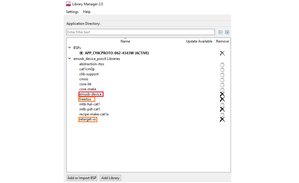
Launch the ModusToolbox Library Manager, click Add Library button and select the emUSB-Device. This step is required only if the ModusToolbox IDE is used. Otherwise, ensure that the emUSB-Device middleware is included in your project.

PSE84 Devices:
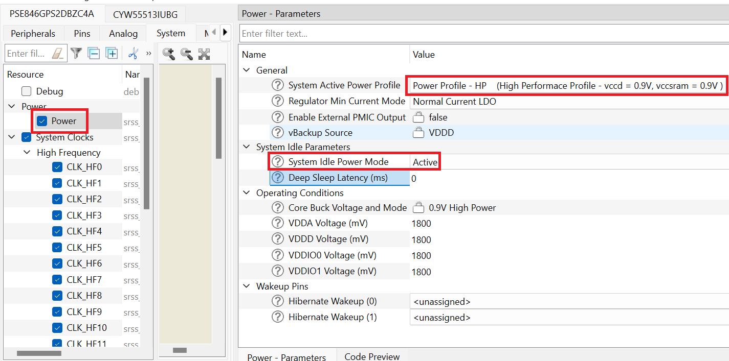
Switch to the System tab (#2.1).
Initialize retarget-io to use the debug UART port:
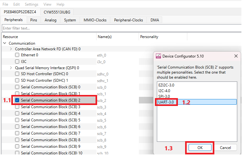
For PSE84 devices: Open Device Configurator, select Peripherals, select the desired SCB resource (#1.1), select the UART in the window of choosing the personality (#1.2), click OK (#1.3).
Select the desired name for the SCB (#2.1) and the pins and clock for the SCB (#2.2). The other UART options can be set by default, see the screenshot below.
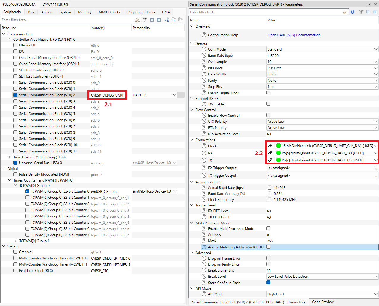
The desired name for the SCB resource is important because the generated structures, defines and variables have the prefix of that name. See below.
Call main_task():
For non-RTOS environments:
Call the main_task() into the main() function.
For RTOS environments:
Create a FreeRTOS task with main_task() using xTaskCreate and start the task scheduler instead of calling main_task():
This section explains the details of the emUSB-Device configuration.
The hardware resources (Pins, clocks, interrupts, timer) required for USB must be configured before the start of USB operation before calling USBD_Init() or in USBD_X_Config(). Interrupts must be configured in the USBD_X_Config() function. Also, USBD_X_EnableInterrupt() and USBD_X_DisableInterrupt() must be implemented when the USBD_OS_USE_USBD_X_INTERRUPT compile time option is enabled.
The implementation template of USBD_X_Config(), USBD_X_EnableInterrupt() and USBD_X_DisableInterrupt() is provided for each device in the Config directory under COMPONENT_*. This template is automatically copied into your project when middleware is added to project. This template does not include the configuration of clock and pins required for USB operation. The configuration of timer is provided. Need to setup provided structures, defines and variables from Device Configurator in USB personality.
For details on Hardware Dependent Configuration, refer to the - SEGGER emUSB-Device User Guide & Reference Manual.
PSE84 Devices Family
The D+/D- pins are dedicated and do not require configuration.
The USB 2.0 specification defines the required bit rate accuracy for the device in section 7.1.11. Ensure that the clock sources for USB meet the requirements.
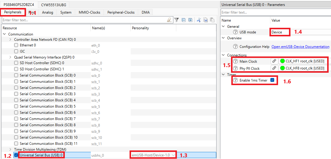
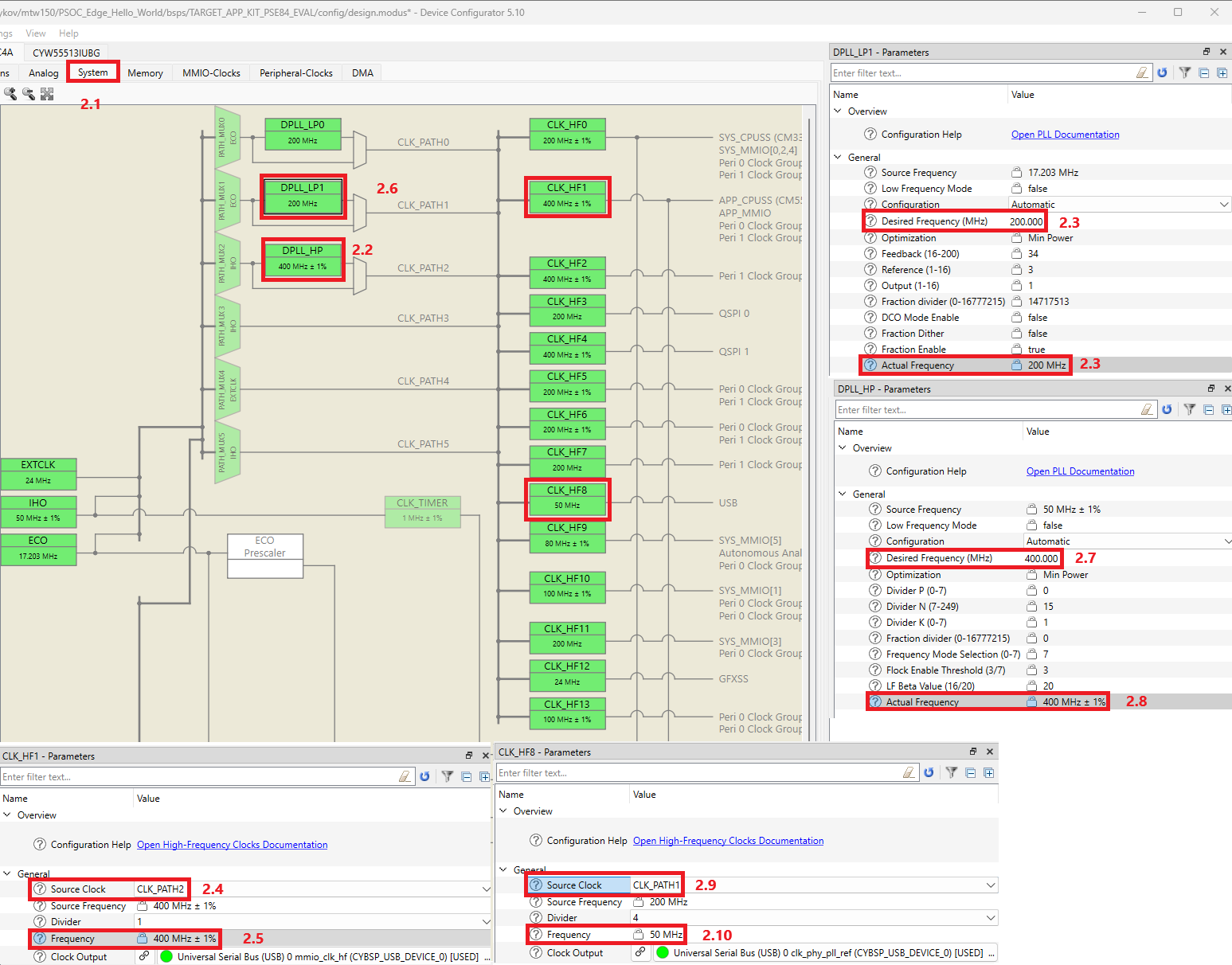
The emUSB-Host/Device personality in the Device Configurator allows for easy configuration of the clocks for USB operation and also check if the clocks meet the requirements. Otherwise, the clocks can be configured manually by PDL/HAL Next APIs for PSE84.
PSE84 Devices Family
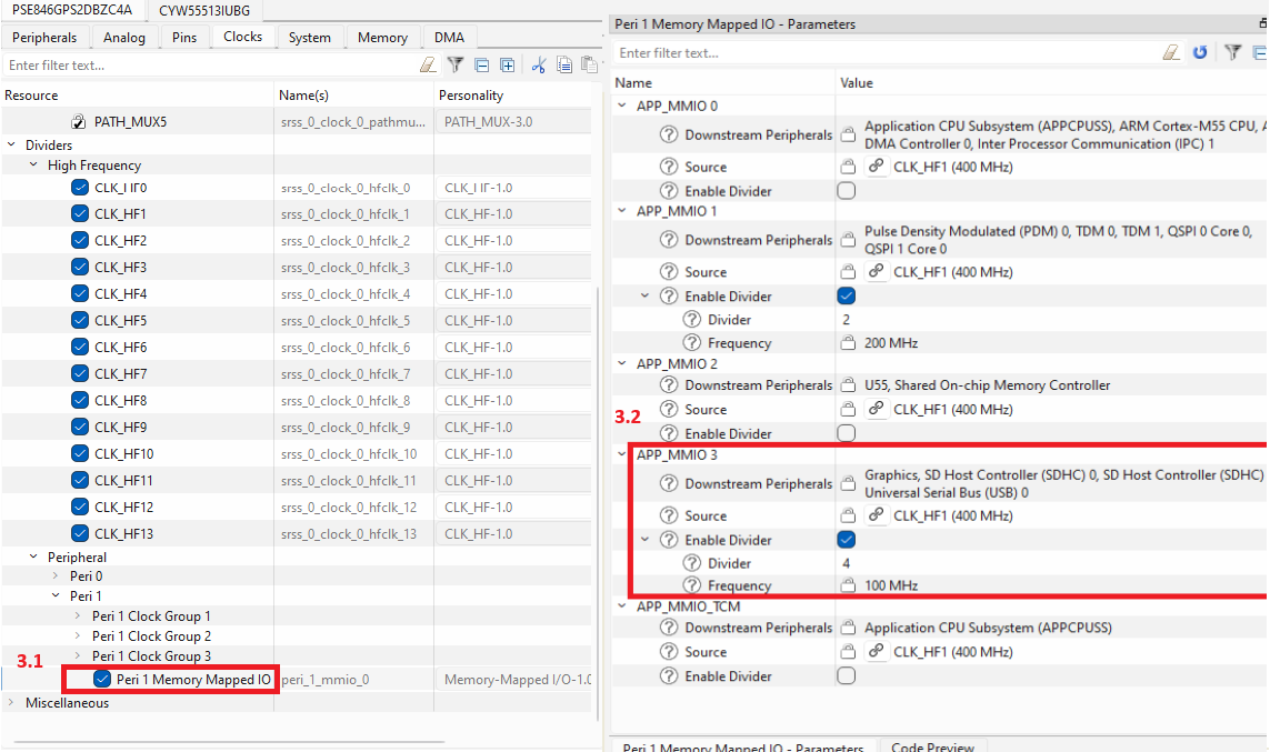
The USB Device requires two clocks for operation:
Also, enable the corresponding Peri Group by the Cy_SysClk_PeriGroupSlaveInit() function from the SysClk driver of mtb-dsl-pse8xxgp.
The interrupt is mandatory for the emUSB-Device Middleware operation. The interrupt priority selection is a part of Application level - the interrupt priority selected in the template files is not suitable for real project. For USB recommended setting the interrupt priority as high as possible.
PSE84 Devices
emUSB-Device use one interrupt source - usbhs_interrupt_usbhsctrl_IRQn. The emUSB-Device can be executed on the CM33 or CM55 core. The interrupt configuration is the same for both cores.
PSE84 Devices Family
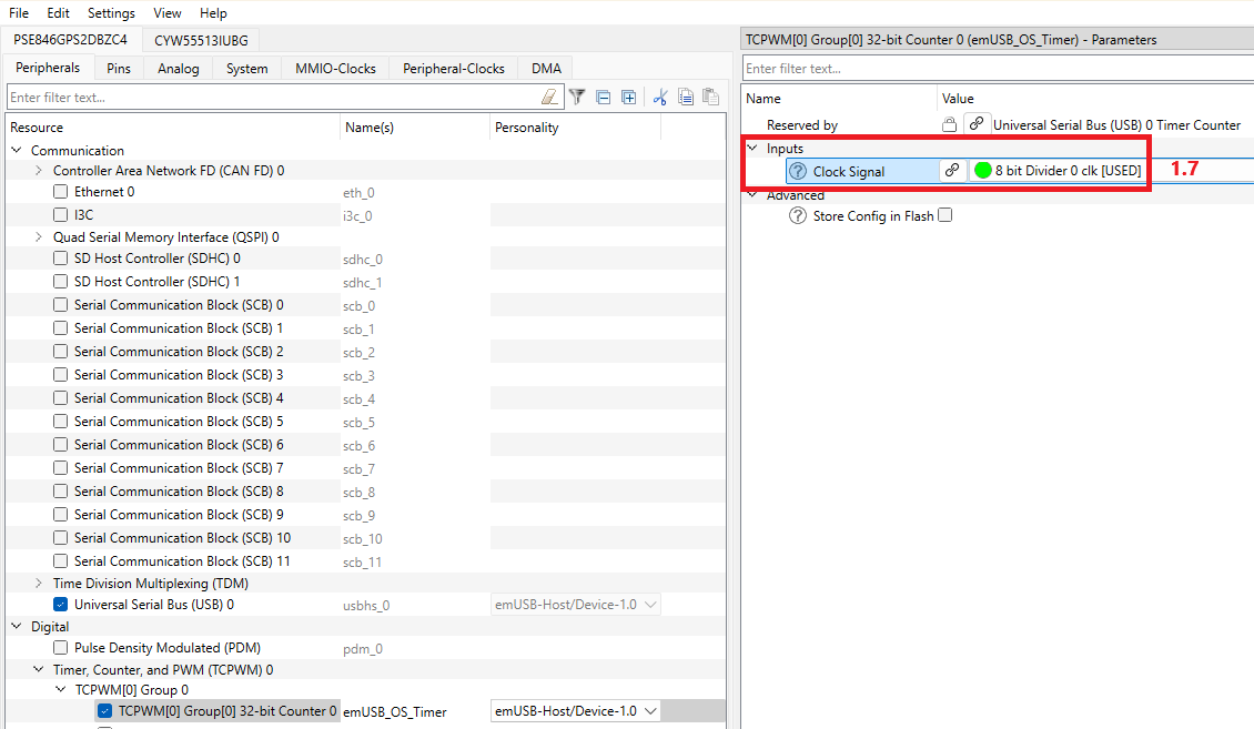
This configuration is for non-RTOS environment. The timer is already configured in the usbd_config.c file for PSE84. But its initialization takes data from the generated code from the Device Configurator USB personality. Enable the "Enable 1ms Times" checkbox, and select the TCPWM set of the clock divider. The prefix name of the structures, defines, and variables set by default for TCPWM is "emUSB_OS_Timer". The prefix can be changed but note that it impacts the generated code used in the export/Config/COMPONENT_PSE84/usbd_config.c file. For details on setting up the timer in the personality, see Quick Start for PSE84 devices.
The debug builds of emUSB-Device allow using the debug message outputs. The template implementation of the message output functions is in export/Config/usbd_config_io.c file. This file is automatically copied into the ModusToolbox project when emUSB-Device middleware is added for the first time by the Library manager. Otherwise, copy this file manually. By default, retarget-io is used for the message output, but message outputs can be redefined to any suitable output way. To disable the default message outputs, set USBD_DISABLE_STANDARD_OUTPUT=1 in the DEFINES variable in the application project Makefile. To provide a custom output method in addition to setting a variable add corresponding API under the #if (USBD_DISABLE_STANDARD_OUTPUT == 1U) condition inside the _puts() function.
For details on Hardware Debug Message Output, refer to the - SEGGER emUSB-Device User Guide & Reference Manual Debugging chapter.
The USB Host can initiate Suspend condition on the USB bus to reduce power consumption of the connected device. emUSB-Device can identify Suspend condition in a few ways. For example: calling USBD_GetState() through a specific time interval (typically 1 ms), by the callback function registered in USBD_RegisterSCHook() or by the other ways supported in the emUSB-Device stack. When Suspend condition is identified, the suspended device must limits the current consumption from VBUS to 0.5 mA. Therefore, put the device into Low-power mode to consume less current. emUSB-Device does not change the microcontroller Power mode by itself. It is the application responsibility to reduce power consumption to meet the requirements. Also, it is the application responsibility to prepare emUSB-Device for low-power mode and detect Resume condition. The preparation of the emUSB-Device middleware for low-power mode and detection of Resume condition differ among devices. Pay attention for the following explanation for the required devices.
Refer to the - SEGGER emUSB-Device User Guide & Reference Manual Low power mode chapter for additional information about the behavior of emUSB-Device in low-power mode.
Typically, the microcontroller enters Deep Sleep or similar mode to achieve the required current consumption, but other approaches are also possible if they exist. The next table shows the recommended low-power modes for Suspend state for each supported device:
| Device family | Recommended low-power mode |
|---|---|
| PSE84 | Sleep |
PSE84 Devices
The USB IP block can operate only in Active and Sleep mode.
Typically, RTOS decide to go to Idle state when no active tasks remain active. Often, the transition into Idle condition is accompanied by entering the microcontroller in one of low-power modes (Depends on RTOS configuration). But the USB device must provide correct responses to all events on the USB bus. The preventing mechanism must be implemented, which does not allow the microcontroller to enter low-power mode when emUSB-Device is not in Suspended state. For example, for FreeRTOS, a custom implementation of vApplicationSleep() must be provided.
emUSB-Device supports the Link Power Management feature like the configuration BESL (Best Effort Service Latency) value and reports on LPM transition on USB lines (L0 <--> L1).
To enable LPM:
Based on the received BESL value, the application can determine the level of the power optimization and select appropriate low-power modes. The behavior of the USB IP block during low-power modes for each device described in Low Power Support.
For more information about LPM, refer to "USB 2.0 Link Power Management Addendum" and "Errata for USB 2.0 ECN: Link Power Management (LPM) - 7/2007" from usb.org.
By default, emUSB-Device requires HAL Next APIs for operation. However, when HAL Next APIs cannot be used in the application, the USBD_USE_PDL option is available. With this macro set to 1, the emUSB-Device middleware will use PDL APIs instead of HAL Next APIs. When USBD_USE_PDL=1, the application must disable the standard debug output (USBD_DISABLE_STANDARD_OUTPUT=1) and, in a non-RTOS environment, provide the custom implementation for USB_OS_GetTickCnt() function (USBD_NORTOS_TICKCNT_ENABLE=0). The USBD_USE_PDL macro must be set in the DEFINES variable in the application project Makefile.
The Middleware provides emUSB-Device as pre-build libraries. The pre-build libraries are selected automatically based on configurations of Makefile configurations. The table below shows the availability of the configuration options.
| Configuration | Options | Make Variable |
|---|---|---|
| Device family | PSE84 | DEVICE_COMPONENTS |
| Build configuration | Debug, Release | CONFIG |
| Core |
| CORE |
| Floating point | hardfp, softfp | VFP_SELECT |
| Toolchain | GCC_ARM, IAR, ARM, LLVM-ARM | TOOLCHAIN |
Some of the parameters/features of emUSB-Device are configured by the compile-time options (like the number of the interface that supports the ISO transfer, etc) during generation of pre-build libraries and cannot change in run-time. Header file USBD_ConfDefaults.h under the USBD directory contains the common compile time options used during pre-build libraries creation. Similarly, USBD_Conf.h under each COMPONENT_<Device family>/CONFIG_< Build configuration> directory contains the compile time options specific to the set of library variants. The compile time options defined in USBD_Conf.h have a higher priority than in USBD_ConfDefaults.h. Most of the compile time options are defined in these two header files but some are not visible like the macro, which define the number of interfaces. This section describes the compile time options not defined in USBD_Conf.h and USBD_ConfDefaults.h.
This table shows the number of supported interfaces for each class between the device families.
| USB Class | PSE84 |
|---|---|
| Audio | 1 |
| Legacy Audio | 1 |
| Bulk | 4 |
| CCID | 1 |
| CDC | 2 |
| HID | 2 |
| MSD | 1 |
| MTP | 1 |
| Printer | 1 |
| VirtualMSD | 1 |
| VSC | Limited by USB_MAX_NUM_IF |
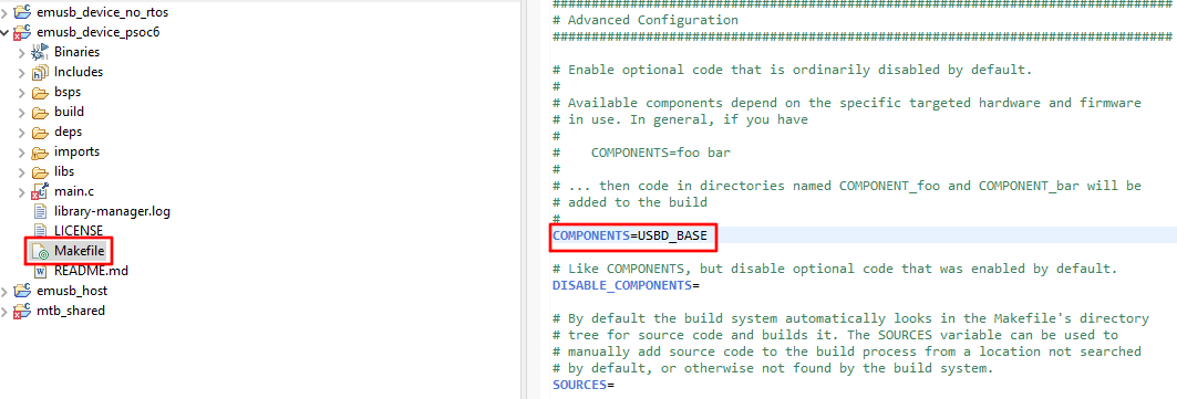
The MSD and MTP are supplied with already implemented storage drivers using emFile. The MSD supports: USB_MSD_StorageByName and USB_MSD_StorageByIndex, the MTP supports: USB_MTP_StorageFS drivers. The implementation of these drivers are present in additional pre-build libraries. By default these libraries are not added to the build, to enable them - add USBD_EMFILE to the COMPONENTS variable in Makefile. The additional pre-build libraries with emFile storage drivers support the three different FAT sub types: FAT12, FAT16 and FAT32. The selection of a specific FAT type is the same as for the emFile middleware - add EMFILE_FAT16 for FAT12/16 or EMFILE_FAT32 for supporting all three sub types to the COMPONENTS variable in Makefile.
The emUSB-device has been already implemented the Target OS Interface for both RTOS and non-RTOS aware environments. Selecting the OS layer implementation is automatic based on the RTOS_AWARE component. To inform the emUSB-Device that an RTOS environment is being used, set the RTOS_AWARE component (COMPONENTS+=RTOS_AWARE).
For the RTOS environment, the OS layer uses the abstraction-rtos library, and as a result, the emUSB-Device can be used with RTOSes supported by the abstraction-rtos library.
Specific implementation of Target OS Interface:
For non-RTOS environment: For PSE84 devices: USB_OS_GetTickCnt() configures one instance of the timer by the driver of HAL Next library for returning the current system time in milliseconds. The timer is started by initializing the emUSB-Device middleware with data from the Universal Serial Bus (USB) personality by checking "Enable 1ms Timer". Universal Serial Bus (USB) personality reserves one of the available TCPWM that has the Timer-Counter setting. For details on the timer usage, see in Quick Start for PSE84 devices.
USB_OS_GetTickCnt() own implementation can be provided due to:
Timer (Timer/Counter) Driver); To do that, set the USBD_NORTOS_TICKCNT_ENABLE macro value to zero in Makefile file.
For details on Target OS Interface, refer to the - SEGGER emUSB-Device User Guide & Reference Manual Target OS Interface chapter.
The Middleware structure:
Note that the emUSB-Device Middleware by Infineon and emUSB-Device stack by Segger have different versions
| Version | Changes | Reason for Change |
|---|---|---|
| 2.1.0 | Updated the emUSB-Device stack to 3.66.5 | New version is available |
| 2.0.0 | Added LLVM compiler support. | Extending the supported features for emUSB-Device middleware |
| Migrated to HAL-Next. | ||
| Updated the emUSB-Device stack to 3.66.0 | New version is available | |
| 1.5.0 | For MSD and MTP classes the already implemented storage drivers are added. These drivers are implemented by emFile APIs. For more details, refer to the Integration with emFile. | Extending the supported features for emUSB-Device middleware |
| Updated the emUSB-Device stack to 3.64.3 | New version is available | |
| 1.4.0 | Add a new driver for PSoC 6 with DMA support. Now for PSoC 6, the total size of all endpoints is not limited by 512 bytes for DMA driver. | Extending the supported features for emUSB-Device middleware |
| Updated the emUSB-Device stack to 3.64.1 | New version is available | |
| Add the props.json file | Improve the integration with the ModusToolbox 3.0+ flow | |
| Update usbd_config.c file for XMC4000 to support OTG. OTG feature is supported in emUSB-Device and emUSB-Host middleware | Extending the supported features for emUSB-Device middleware | |
| 1.3.0 | Added support of Smart Card Device Class (CCID) | Extending the supported features for emUSB-Device middleware |
| Added new Audio class with extended features like compatibility to USB Audio version 2 device class, explicit feedback and others. The legacy Audio class is not recommended to use in new applications. | Extending the supported features for emUSB-Device middleware | |
| Updated the emUSB-Device stack to 3.62.0 | New version is available | |
| Added the new compile time option to allow use emUSB-Device without HAL library. For details, refer to the Only PDL APIs support. | Extending the supported features for emUSB-Device middleware | |
| The maximum number of alternative interfaces are increased from 2 to 4 for all supported device families (See the USB_MAX_NUM_ALT_IF macro in the USB_Conf.h file). | ||
| Minor documentation updates | ||
| 1.2.0 | Provided support for XMC4000 devices. | |
| Updated the emUSB-Device stack to 3.60.1 | New version is available | |
| Added a new section in the documentation Pre-build libraries configuration | ||
| Minors improvements in OS layer | ||
| 1.1.0 | Updated the emUSB-Device stack to 3.58.0 | New version is available |
| Added support of Audio class | Extending the supported features for emUSB-Device middleware | |
| The OS layer uses abstraction-rtos APIs instead of FreeRTOS. This means that emUSB-Device can be used with RTOS supported by abstraction-rtos including FreeRTOS | Extend the number of supported RTOS | |
The next compile time options were updated for PSOC6 devices:
| Extending the supported features for PSOC6 devices | |
| Added remote wake-up functionality for PSOC6 devices | Extending the supported features for PSOC6 devices | |
| Updated the implementation of Debug Message Output. The usbd_config_io.c file became more friendly for updating and a USBD_DISABLE_STANDARD_OUTPUT macro was added. For details, refer to Debug Message Output | Improved the usability of Debug Message Output | |
| Added a new section in the documentation Link Power Management (LPM) | ||
| Minor documentation updates | ||
| 1.0.1 | Updating the LICENSE file | |
| 1.0.0 | Initial release of emUSB-Device stack 3.52.2 |