Cypress CSDADC Middleware Library 2.10
Cypress CSDADC Middleware Library 2.10 Documentation

The CSDADC middleware is the CYPRESS™ ADC solution, which uses the CSD HW block.The CSD HW block is mainly used to implement the touch sense applications and proximity sensors (refer to the CAPSENSE™ Middleware API Reference Guide), but can also be used to implement the ADC, which is especially useful for the devices that do not include another hardware option to implement the ADC. CSDADC provides the following measurement capabilities:

  • Voltage monitoring on multiple external channels. Any GPIO that can be connected to AMUX-B (refer to the particular device datasheet for information) can be an input to the CSDADC under software control.
  • Voltage monitoring on AMUX-B.
  • Device supply voltage (VDDA) monitoring without the need of explicitly connecting VDDA to a GPIO input of the ADC. This capability can be used to measure battery voltages and/or change VDDA-dependent parameters of the ADC during run-time.

The listed capabilities are making the CSDADC useful for a variety of applications, including home appliances, automotive, IoT, and industrial applications. The CSDADC middleware can use the same CSD HW block with other CSD-based middleware (CAPSENSE™, CSDIDAC, etc) in the time-multiplexed manner.

Features:

  • ADC with 8- and 10-bit resolution
  • Two input measurement ranges: GND to VREF and GND to VDDA
  • Two operation modes: Continuous conversion and Single-shot conversion

General Description

Include cy_csdadc.h to get access to all functions and other declarations in this library. The Quick Start Guide is offered in this API Reference Guide.

Refer to the Supported Software and Tools for the compatibility information.

Refer to the Changelog for the differences between the Middleware versions.

The Changelog also describes the impact of the changes to your code.

The CSD HW block enables multiple sensing capabilities on PSoC™ devices including the self-cap and mutual-cap capacitive touch-sensing solutions, a 10-bit ADC, IDAC, and Comparator. The CSD driver is a low-level peripheral driver, a wrapper to manage access to the CSD HW block. Any middleware access to the CSD HW block happens through the CSD Driver.

The CSD HW block can support only one function at a time. However, all supported functionality (like CAPSENSE™, CSDADC, etc.) can be time-multiplexed in a design. I.e. you can save the existing state of the CAPSENSE™ middleware, restore the state of the CSDADC middleware, perform ADC measurements, and then switch back to the CAPSENSE™ functionality. For more details and code examples, refer to the description of the Cy_CSDADC_Save() and Cy_CSDADC_Restore() functions.

capsense_solution.png
CAPSENSE™ Solution

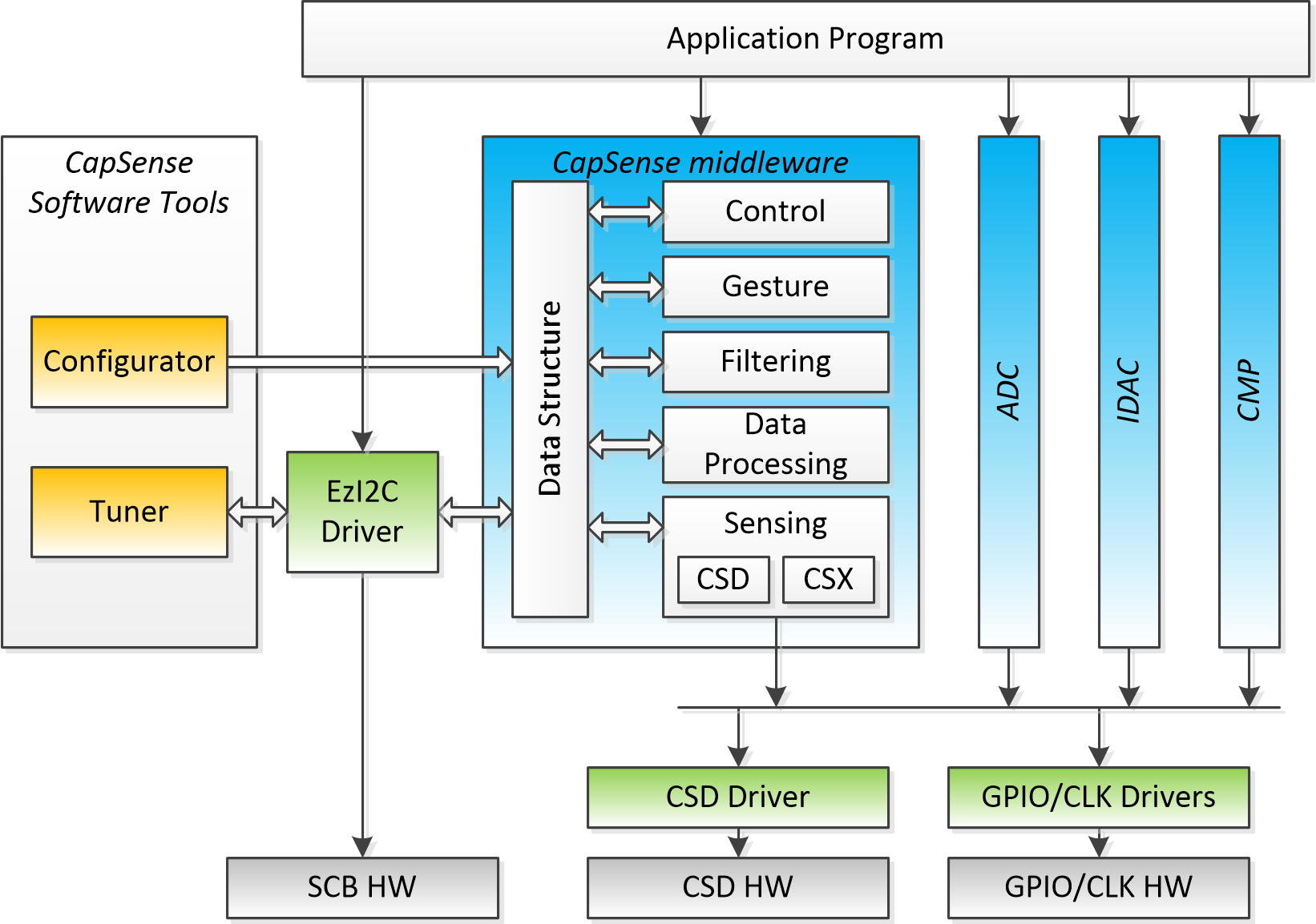
This section describes only the CSDADC middleware. Refer to the corresponding sections for documentation of other middleware supported by the CSD HW block. The CSDADC library is designed to use with the CSD driver. The application program does not need to interact with the CSD driver and/or other drivers such as GPIO or SysClk directly. All of that is configured and managed by the middleware.

The CSDADC API is described in the following sections:

Warning
I2C transactions during ADC conversions may lead to measurement result distortions. Perform ADC conversions and I2C communications in Time-sharing mode.

Quick Start Guide

CYPRESS™ CSDADC middleware can be used in various Development Environments such as ModusToolbox™, MBED, etc. Refer to the Supported Software and Tools. The quickest way to get started is using the Code Examples. Infineon Technologies continuously extends their portfolio of code examples at the Infineon Technologies and at the Infineon Technologies GitHub.

This quick start guide assumes that the environment is configured to use PSoC™ 6 (psoc6pdl) or PSoC™ 4 (psoc4pdl) Peripheral Driver Library (depending on the platform used). Also, include the Peripheral Driver Library into the project.

The following steps are required to set up the CSDADC and to run the measurement:

  1. Set up the CSDADC configuration manually or by using the Device Configurator as described in the Configuration Considerations section.
    Note
    Put the CSDADC name to the Alias field of the CSD resource if the Device Configurator is used.
  2. Include cy_csdadc.h to get access to all CSDADC API and cy_pdl.h to get access to API of peripheral drivers according to the example below:
    #include "cy_pdl.h"
    #include "cy_csdadc.h"
  3. Include the cycfg.h file to access the System Configuration if the Device Configurator is used for the initialization code generation:
    #include "cycfg.h"
  4. Declare the 'cy_csdadc_context' variable as per example below:
    /* CSDADC context declaration */
    cy_stc_csdadc_context_t cy_csdadc_context;
  5. Declare and initialize the CSDADC_ISR_cfg variable as per example below:
    PSoC™ 6   PSoC™ 4
    const cy_stc_sysint_t CSDADC_ISR_cfg =
    {
    .intrSrc = csd_interrupt_IRQn, /* The interrupt source is the CSD interrupt */
    .intrPriority = 7u, /* The interrupt priority is 7 */
    };
    const cy_stc_sysint_t CSDADC_ISR_cfg =
    {
    .intrSrc = csd_interrupt_IRQn, /* The interrupt source is the CSD interrupt */
    .intrPriority = 3u, /* The interrupt priority is 3 */
    };
  6. Define the CSDADC interrupt handler according to the example below:
    static void CSDADC_Interrupt(void)
    {
    Cy_CSDADC_InterruptHandler(CSDADC_HW, &cy_csdadc_context);
    }
  7. Update the main() routine with the following code:
    uint32_t ch0Result;
    uint32_t ch1Result;
    /* The code below defines a mask to enable conversion on Channel-0 and Channel-1.
    * Optionally, the generated by Device Configurator CSDADC_CSDADC_ALL_CHAN_MASK
    * macro can be used to allow scanning of all configured channels.
    */
    uint32_t channelsMask = 0x03u; // (1u << 0u) | (1u << 1u)
    /* UNCOMMENT THE FOLLOWING LINE if Device Configurator is used
    * to generate the initialization code.
    * Use the cybsp_init() function instead of the init_cycfg_all() one
    * if the Board Support Package (BSP) is available.
    */
    //init_cycfg_all();
    /* UNCOMMENT THE FOLLOWING LINE in case of manual implementation of the
    * initialization code to assign the Peripheral Clock Divider to the CSD HW block
    */
    //Cy_SysClk_PeriphAssignDivider(PCLK_CSD_CLOCK, CY_SYSCLK_DIV_16_BIT, PERI_DIV_INDEX_0);
    /* UNCOMMENT THE FOLLOWING BLOCK OF CODE in case of manual implementation of the
    * initialization code to set configuration of the HSIOM_AMUX_SPLIT_CTL switches
    */
    //#if(1u == CY_IP_MXS40IOSS_VERSION)
    // HSIOM->AMUX_SPLIT_CTL[4] = HSIOM_AMUX_SPLIT_CTL_SWITCH_BB_SL_Msk |
    // HSIOM_AMUX_SPLIT_CTL_SWITCH_BB_SR_Msk;
    //#elif(2u == CY_IP_MXS40IOSS_VERSION)
    // HSIOM->AMUX_SPLIT_CTL[4] = HSIOM_V2_AMUX_SPLIT_CTL_SWITCH_BB_SL_Msk |
    // HSIOM_V2_AMUX_SPLIT_CTL_SWITCH_BB_SR_Msk;
    //#elif(1u == CY_IP_M0S8IOSS_VERSION)
    // /* No action is needed when P0 is configured as ADC input */
    //#else
    // #error Not supported device
    //#endif
    /* Captures the CSD HW block and Initializes it to the default state */
    Cy_CSDADC_Init(&CSDADC_csdadc_config, &cy_csdadc_context);
    /* Initializes the CSDADC interrupt */
    Cy_SysInt_Init(&CSDADC_ISR_cfg, &CSDADC_Interrupt);
    NVIC_ClearPendingIRQ(CSDADC_ISR_cfg.intrSrc);
    NVIC_EnableIRQ(CSDADC_ISR_cfg.intrSrc);
    /* Initializes the CSDADC firmware modules */
    Cy_CSDADC_Enable(&cy_csdadc_context);
    for(;;)
    {
    if (CY_CSDADC_SUCCESS == Cy_CSDADC_StartConvert(CY_CSDADC_SINGLE_SHOT, channelsMask, &cy_csdadc_context))
    {
    while (CY_CSDADC_SUCCESS != Cy_CSDADC_IsEndConversion(&cy_csdadc_context))
    {
    /* Waits for the end of conversions */
    }
    /* Stores the Channel-0 measurement result to the ch0Result variable */
    ch0Result = Cy_CSDADC_GetResultVoltage(0u, &cy_csdadc_context);
    /* Stores the Channel-1 measurement result to the ch1Result variable */
    ch1Result = Cy_CSDADC_GetResultVoltage(1u, &cy_csdadc_context);
    }
    else
    {
    /* Insert the error handle code here, an example is given below */
    CY_ASSERT(0u);
    }
    }

Configuration Considerations

The CSDADC middleware operates on the top of the CSD Driver included in the PSoC™ 6 (or PSoC™ 4) Peripheral Driver Library (psoc6pdl/psoc4pdl). Refer to the "CSD (CAPSENSE™ Sigma Delta)" section of the PSoC™ 6 Peripheral Driver Library (psoc6pdl) (or PSoC™ 4 Peripheral Driver Library (psoc4pdl)) API Reference Manual. This Configuration Considerations section guides how to set up the CSDADC middleware for the operation with the following parameters:

  1. Device VDDA: 3.3V.
  2. Device Peri Clock frequency: 48MHz.
  3. Desired Resolution: 10 bit.
  4. Desired Measurement Range: GND to VDDA.
  5. Desired Number of Input Channels: 2.
Note
In this guide, there are different pins used for PSoC™ 6 and PSoC™ 4 platforms. Refer to the table below to select the correct pins for the project.
Channel PSoC™ 6 PSoC™ 4
0 P6[2] P0[2]
1 P6[3] P0[3]

There are two approaches to the CSDADC Middleware configuration:

  1. Use ModusToolbox™ Device Configurator Tool to generate initialization code
  2. Implement the initialization code manually

Generation of the initialization code using the ModusToolbox™ Device Configurator Tool which is part of the ModusToolbox™, greatly simplifies the PSoC™ configuration. The ModusToolbox™ Device Configurator Tool provides the user interface to set up and automatically generate the initialization code (including analog routing) and configuration structures.

Manual implementation of the initialization code (including analog routing) and configuration structures is recommended for expert Users only. This will include the code for the following settings which in case of the Device Configurator usage are generated automatically based upon the settings entered in its UI:

  • Assigning the Peripheral Clock Divider.
  • Configuring the HSIOM_AMUX_SPLIT_CTL switches to route signal from input pins configured as the CSDADC channels to the CSD HW block.
  • Declaration and initialization of the CSDADC configuration structure.
  • Declaration and initialization of the CSD HW driver context structure.
  • Definition of the of the CSD HW block base address.

Use ModusToolbox™ Device Configurator Tool to generate initialization code

The following steps are required to generate the initialization code using the ModusToolbox™ Device Configurator Tool :

  1. Launch the ModusToolbox™ Library Manager and enable the CSDADC middleware. This step is required only if the ModusToolbox™ IDE is used. Otherwise, ensure the CSDADC Middleware is included in your project.
  2. Launch the ModusToolbox™ Device Configurator.
  3. Switch to the System tab. Configure the CLK_PERI frequency to achieve 48MHz (you may need to change the FLL or PLL frequency) and set the VDDA voltage to 3.3V in Power/MCU Personality.
  4. Switch to the Peripherals tab (#1 on figure below). Enable the CSD personality under System (#2 on figure below) and enter Alias (#3 on figure below). We use CSDADC in Quick Start Guide.
  5. Go to the Parameters Pane and configure the CSD Personality:
    • Assign the peripheral clock divider by using the Clock combo box(#4 on figure below). Any free divider can be used.
    • Set the Enable CSDADC check box (#5 on figure below).
    • Configure the CSDADC with the desired parameters per Configuration Considerations (#5 on figure below).
    • Assign the CSDADC Channels to pins per Configuration Considerations (#6 on figure below).
  6. Perform File->Save to generate initialization code.
csdadc_config.png
CSDADC configuration
Note
The screenshot above provides the configuration for the PSoC™ 6 platform. For PSoC™ 4, the only difference is the CSDADC Channels configuration (#6 on figure above).

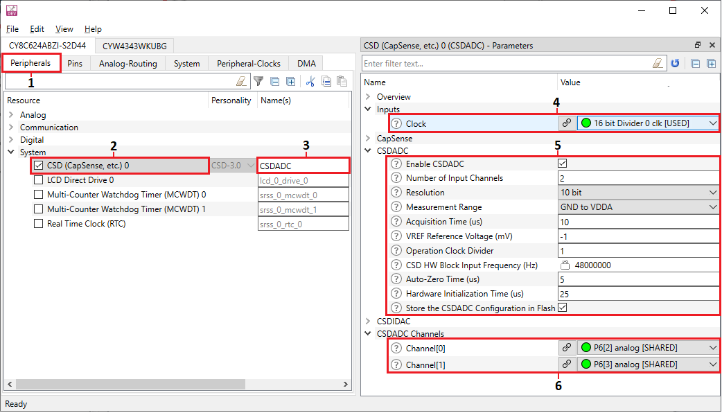
Now, all required CSDADC initialization code and configuration prerequisites will be generated:

  • The Peripheral Clock Divider assignment and analog routing are parts of the init_cycfg_all() routine. Place the call of the init_cycfg_all() function before using any CSDADC API functions to ensure initialization of all external resources required for the CSDADC operation. Refer to the main() routine code snippet in Quick Start Guide
  • The CSDADC configuration structure declaration in the cycfg_peripherals.h file and its initialization in the cycfg_peripherals.c file. The variable name is <Alias_Name>_csdadc_config.
  • The CSD HW driver context structure declaration in the cycfg_peripherals.h file and its initialization in the cycfg_peripherals.c file. The variable name is cy_csd_<CSD_Block_Index>_context.
  • The CSD HW block base address definition is in the cycfg_peripherals.h file.
  • The definition name is <Alias_Name>_HW.

The generated code will be available under the GeneratedSource folder.

Refer to Quick Start Guide section for the application layer code required to set up CSDADC and run the measurement.

Implement the initialization code manually

The steps required to implement the initialization code manually:

  1. Launch the ModusToolbox™ Library Manager and enable the CSDADC middleware. This step is required only if the ModusToolbox™ IDE is used. Otherwise, ensure the CSDADC Middleware is included in your project.
  2. Define the CSD HW block base address and programmable clock divider index. See the code example below:
    #define CSDADC_HW (CSD0)
    #define PERI_DIV_INDEX_0 (0u)
  3. Declare the CSD HW driver context structure and initialize the lockKey field with the CY_CSD_NONE_KEY value. See the code example below:
    cy_stc_csd_context_t cy_csd_context =
    {
    .lockKey = CY_CSD_NONE_KEY, /* Initialization of the lockKey with the CY_CSD_NONE_KEY
    is required */
    };
  4. Declare the CSDADC configuration structure and initialize it according to the desired parameters. See the code example below:
    PSoC™ 6   PSoC™ 4
    static const cy_stc_csdadc_ch_pin_t chList[2u] =
    {
    {GPIO_PRT6, 2u}, /* Assign Channel-0 to P6[2] */
    {GPIO_PRT6, 3u} /* Assign Channel-1 to P6[3] */
    };
    static const cy_stc_csdadc_ch_pin_t chList[2u] =
    {
    {GPIO_PRT0, 2u}, /* Assign Channel-0 to P0[2] */
    {GPIO_PRT0, 3u} /* Assign Channel-1 to P0[3] */
    };
    const cy_stc_csdadc_config_t CSDADC_csdadc_config =
    {
    .ptrPinList = chList, /* Points to the array with configured CSDACD Ports/Pins */
    .base = CSDADC_HW, /* The CSD0 HW block is selected for CSDADC operation */
    .csdCxtPtr = &cy_csd_context, /* Points to the CSD driver context structure */
    .cpuClk = 48000000u, /* Provides an absolute CPU clock frequency in the current design (configured to 48MHz) */
    .periClk = 48000000u, /* Provides an absolute Peri clock frequency in the current design (configured to 48MHz) */
    .vref = -1, /* Sets auto-selection of the reference voltage */
    .vdda = 3300u, /* Provides Supply Voltage in the current design (configured to 3.3V) */
    .calibrInterval = 0u, /* Reserved for further enhancements */
    .range = CY_CSDADC_RANGE_VDDA, /* Selects the measurement range (configured to GND to VDDA) */
    .resolution = CY_CSDADC_RESOLUTION_10BIT, /* Selects the measurement resolution (configured to the 10-bit resolution) */
    .periDivTyp = CY_SYSCLK_DIV_16_BIT, /* Pass the type of clock divider, used to clock the CSD HW block.
    On the application layer, assign the same type divider by using the
    Cy_SysClk_PeriphAssignDivider() function. The CSDADC middleware requires information
    about the used divider to be able to control it in the run time (enable/disable, change value) */
    .numChannels = 2u, /* Configured CSDADC MW to measure the voltage on two channels */
    .idac = 31u, /* Reserved for further enhancements */
    .operClkDivider = 1u, /* Defines the value to be set by CSDADC in the run time to the clock divider, assigned on
    the application layer by using the Cy_SysClk_PeriphAssignDivider() function. The Max supported
    clock frequency for the CSD HW block is 50 MHz. The divider value "1" is used,
    because in the current case the Peri Clock frequency is 48 MHz */
    .azTime = 5u, /* Configures Auto-zero time to 5 us (as default) */
    .acqTime = 10u, /* Configures Acquisition time to 10 us (as default) */
    .csdInitTime = 25u, /* Configures the CSD0 wake-up initialization time to 25 us (as default) */
    .idacCalibrationEn = 0u, /* Reserved for further enhancements */
    .periDivInd = PERI_DIV_INDEX_0, /* Pass the index of the clock divider used to clock the CSD HW block.
    Assign divider with the same index on the application layer by using the
    Cy_SysClk_PeriphAssignDivider() function. The CSDADC middleware requires information
    about the used divider to be able to control it in the run time (enable/disable, change value) */
    };
  5. Assign the Peripheral Clock Divider to the CSD HW block. See the code example below and refer to the main() routine code snippet in Quick Start Guide
    /*
    * The user responsibility is to assign the peripheral clock divider to the
    * CSD HW block on application layer. Any free divider of any type can be used.
    *
    * PCLK_CSD_CLOCK - connect divider to the CSD HW block
    * CY_SYSCLK_DIV_16_BIT - use 16-bit divider
    * PERI_DIV_INDEX_0 - select divider with index #0
    */
    Cy_SysClk_PeriphAssignDivider(PCLK_CSD_CLOCK, CY_SYSCLK_DIV_16_BIT, PERI_DIV_INDEX_0);
  6. Set the configuration of the HSIOM_AMUX_SPLIT_CTL switches to route signal from input pins configured as the CSDADC channels to the CSD HW block. The AMUX_SPLIT_CTL[4] switches are closed to connect port P6 with the CSD HW block (for the PSoC™ 6 platform). Refer to the Technical Reference Manual (TRM) for more information regarding the analog interconnection. See the code example below and refer to the main() routine code snippet in Quick Start Guide.

    Note
    Using P0[2] and P0[3] in the PSoC™ 4 example configuration does not require configuring HSIOM_AMUX_SPLIT_CTL. Refer to the TRM for more information about the other pins.
    #if(1u == CY_IP_MXS40IOSS_VERSION)
    HSIOM->AMUX_SPLIT_CTL[4] = HSIOM_AMUX_SPLIT_CTL_SWITCH_BB_SL_Msk | /* Closes the left AMUX-B switch of AMUX splitter #4 */
    HSIOM_AMUX_SPLIT_CTL_SWITCH_BB_SR_Msk; /* Closes the right AMUX-B switch of AMUX splitter #4 */
    #elif(2u == CY_IP_MXS40IOSS_VERSION)
    HSIOM->AMUX_SPLIT_CTL[4] = HSIOM_V2_AMUX_SPLIT_CTL_SWITCH_BB_SL_Msk | /* Closes the left AMUX-B switch of AMUX splitter #4 */
    HSIOM_V2_AMUX_SPLIT_CTL_SWITCH_BB_SR_Msk; /* Closes the right AMUX-B switch of AMUX splitter #4 */
    #elif(1u == CY_IP_M0S8IOSS_VERSION)
    /* No action is needed when P0 is configured as ADC input */
    #else
    #error Not supported device
    #endif

    Refer to Quick Start Guide section for the application layer code required to set up CSDADC and run the measurement.

Use Cases

This section provides descriptions and links to additional documentation for some specific CSDADC use cases.

Low Power Design

The CSD HW block and CSDADC middleware can operate in CPU active and CPU sleep power modes. It is also possible to switch between low power and ultra low power system modes. The CSD HW block interrupt can wake-up the CPU from sleep mode. In System Deep Sleep and Hibernate power modes, the CSD HW block is powered off and CSDADC conversions are not performed. When the device wakes up from CPU/System Deep Sleep, the CSD HW block resumes operation without re-initialization and the CSDADC conversions can be continued with configuration set before CPU/System Deep Sleep transition. When the device wakes up from System Hibernate power mode, the CSD HW block does not retain configuration and CSDADC requires re-initialization. If the user performs communication to transmit CSDADC results via I2C, UART etc., transitions to CPU sleep, Deep Sleep or Hibernate modes are performed with recommendations both for CSDADC and communications' drivers/middleware.

Note
  1. CPU can seamlessly enter and exit CPU sleep mode while the CSD HW block is busy. However, do not put the CSD HW block into block low power mode during the conversion as it may lead to unexpected behavior.
  2. Entering CPU Deep Sleep mode does not mean that the device enters System Deep Sleep. For more detail about switching to System Deep Sleep, refer to the device TRM.
  3. The analog start-up time for the CSD HW block is 25 us. Initiate any kind of conversion only after 25 us from System Deep Sleep/Hibernate exit.

Refer to the Cy_CSDADC_DeepSleepCallback() function description and to the SysPm (System Power Management) driver documentation for the low power design considerations.

Sleep mode
The CSD HW block can operate in the CPU sleep mode. The user can start CSDADC and move the CPU into Sleep mode. After every conversion, the CPU is woken-up by the CSD interrupt, the results are read, and the CPU goes to sleep again to reduce a power consumption. After the whole conversion cycle completes, the user can read the results, process them, and start a new cycle. Then, the user configures the CSDADC middleware as described in Configuration Considerations, and updates the main() routine with the following code:

/* Scenario: There is a need to measure two input voltages
* while CPU is in Sleep mode during conversions
*/
/* ... */
for (;;)
{
/* Starts CSDADC measuring of the two input channel voltages */
if (CY_CSDADC_SUCCESS == Cy_CSDADC_StartConvert(CY_CSDADC_SINGLE_SHOT, channelsMask, &cy_csdadc_context))
{
while (CY_CSDADC_SUCCESS != Cy_CSDADC_IsEndConversion(&cy_csdadc_context))
{
/*
* Goes to CPU Sleep mode and waits for a CSDADC interrupt.
* CSDADC handles the interrupt and CPU enters Sleep mode again.
* The results are being read and proccessed after the whole
* conversion cycle completion.
*/
#if (defined(CY_IP_MXS40SRSS))
if(CY_SYSPM_SUCCESS != Cy_SysPm_CpuEnterSleep(CY_SYSPM_WAIT_FOR_INTERRUPT))
{
/* You can place error handler code here */
}
#endif
#if (defined(CY_IP_S8SRSSLT))
if(CY_SYSPM_SUCCESS != Cy_SysPm_CpuEnterSleep())
{
/* You can place error handler code here */
}
#endif
}
/* Stores the Channel-0 measurement result to the ch0Result variable */
ch0Result = Cy_CSDADC_GetResultVoltage(0u, &cy_csdadc_context);
/* Stores the Channel-1 measurement result to the ch1Result variable */
ch1Result = Cy_CSDADC_GetResultVoltage(1u, &cy_csdadc_context);
/*
* Insert here a CSDADC data processing here, because the data will be lost
* after the next Sleep entering
*/
}
else
{
/* You can place error handler code here */
}
}

Deep Sleep mode
To use the CSDADC middleware in the CPU/System Deep Sleep mode, the user configures a wake-up source (e.g. a pin, WDT, LPC or any other entities that are active in CPU/System Deep Sleep mode), configures the CSDADC middleware as described in Configuration Considerations, configures CSDADC and other drivers' and middleware's (if presented) Deep Sleep Callback structures, registers callbacks, and updates the main() routine with the following code:

/* CSDADC DeepSleep Callback parameters structure */
cy_stc_syspm_callback_params_t CSDADC_deepSleepParamStr =
{
CSDADC_HW, /* Points to the CSD HW block base */
&cy_csdadc_context, /* Points to the CSDADC context structure */
};
/* CSDADC DeepSleep Callback structure */
cy_stc_syspm_callback_t CSDADC_deepSleepCallbackStr =
{
&Cy_CSDADC_DeepSleepCallback, /* Points to the CSDADC Callback function */
CY_SYSPM_DEEPSLEEP, /* The Callback type */
0u, /* The skip modes mask */
&CSDADC_deepSleepParamStr, /* Points to the Callback parameters structure */
NULL, /* Reserved */
10u, /* The callback priority, can be from 1 (the highest) to 255 (the lowest) */
};
/* Scenario: There is a need to measure two input voltages one time
* per one wake-up event, and the rest of time the CPU should be in Deep Sleep mode */
/* ... */
/* Registers CSDADC DeepSleep Callback */
if (true != Cy_SysPm_RegisterCallback(&CSDADC_deepSleepCallbackStr))
{
/* You can place error handler code here */
}
/* ... */
for (;;)
{
/* Waits for the conversions completion */
if (CY_CSDADC_SUCCESS == Cy_CSDADC_IsEndConversion(&cy_csdadc_context))
{
/* Stores the Channel-0 measurement result to the ch0Result variable */
ch0Result = Cy_CSDADC_GetResultVoltage(0u, &cy_csdadc_context);
/* Stores the Channel-1 measurement result to the ch1Result variable */
ch1Result = Cy_CSDADC_GetResultVoltage(1u, &cy_csdadc_context);
/*
* Insert CSDADC data processing here, because the data will be lost
* after the next DeepSleep entering
*/
/* After the CSDADC data proccessing completion, the CPU goes to Deep Sleep
* and waits for an interrupt. It is the user's responsibility
* to provide an interrupt source for a reliable CPU wake-up.
*/
#if (defined(CY_IP_MXS40SRSS))
if(CY_SYSPM_SUCCESS != Cy_SysPm_CpuEnterDeepSleep(CY_SYSPM_WAIT_FOR_INTERRUPT))
{
/* You can place error handler code here */
}
#endif
#if (defined(CY_IP_S8SRSSLT))
if(CY_SYSPM_SUCCESS != Cy_SysPm_CpuEnterDeepSleep())
{
/* You can place error handler code here */
}
#endif
/* Wakes up CSDADC after a successful exit from Deep Sleep */
Cy_CSDADC_Wakeup(&cy_csdadc_context);
/*
* After Deep Sleep, the CPU and CSD HW block wake up and the CSDADC starts with measuring the two input-channel voltages
*/
if (CY_CSDADC_SUCCESS != Cy_CSDADC_StartConvert(CY_CSDADC_SINGLE_SHOT, channelsMask, &cy_csdadc_context))
{
/*
* You can place error handler code here.
* A software watchdog can be inserted here as well
* to prevent a CSDADC hangout.
*/
}
}
else
{
/*
* Insert here some code, that can be done during
* CSDADC conversions (if it is needed)
*/
}
}

ADC calibration

Refer to the Cy_CSDADC_Calibrate() function description for the CSDADC calibration considerations. Cy_CSDADC_Enable() performs first-time calibration at the start of CSDADC operation. Periodical re-calibrations are required to keep the measurement results accurate.

Time-multiplexing operation of CSDADC and CAPSENSE™

Refer to the Cy_CSDADC_Save() and Cy_CSDADC_Restore() functions descriptions to implement the time-multiplexing operation of CSDADC and CAPSENSE™ by using a common CSD HW block.

Supported Software and Tools

This version of the CSDADC Middleware was validated for the compatibility with the following Software and Tools:

Software and Tools Version
ModusToolbox™ Software Environment 2.4.0
- ModusToolbox™ Device Configurator 3.10
- ModusToolbox™ CSD Personality for PSoC™ 6 in Device Configurator 2.0
- ModusToolbox™ CSD Personality for PSoC™ 4 in Device Configurator 1.1
PSoC™ 6 Peripheral Driver Library (PDL) 2.4.0
PSoC™ 4 Peripheral Driver Library (PDL) 1.6.0
GCC Compiler 10.3.1
IAR Compiler 8.42.1
Arm Compiler 6 6.13
MBED OS 5.13.1
FreeRTOS 10.0.1

Update to Newer Versions

Consult Changelog to learn about the design impact of the newer version. Set up your environment in accordance with Supported Software and Tools. You might need to re-generate the configuration structures for either the device initialization code or the middleware initialization code.

Ensure:

  • The specified version of the ModusToolbox™ Device Configurator and the CSD personality are used to re-generate the device configuration.
  • The toolchains are set up properly for your environment per the settings outlined in the Supported Software and Tools.
  • The project is re-built once the the toolchains are configured and the configuration is completed.

MISRA-C Compliance

The Cy_CSDADC library has the following specific deviations:

MISRA Rule Rule Class (Required/Advisory) Rule Description Description of Deviation(s)
2.5 A A project should not contain unused macro declarations. The middleware library provides an API to the hardware. The macro is part of the API, which is defined for the application-level only.
4.8 A If a pointer to a structure or union is never dereferenced within a translation unit, then the implementation of the object should be hidden. The middleware library uses data structures defined in the PDL library.
4.9 A A function should be used in preference to a function-like macro where they are interchangeable. Deviated since function-like macros are used to allow more efficient code.
5.8 R Identifiers that define objects or functions with external linkage shall be unique. During the code analysis, the same source files are compiled multiple times with device-specific options. All object and function identifiers are unique for each specific run.
5.9 R Identifiers that define objects or functions with internal linkage should be unique. During the code analysis, the same source files are compiled multiple times with device-specific options. All object and function identifiers are unique for each specific run.
8.7 A Functions and objects should not be defined with external linkage if they are referenced in only one translation unit. During the code analysis, the same source files are compiled multiple times with device-specific options. All object and function identifiers are unique for each specific run.
8.13 A A pointer should point to a const-qualified type whenever possible This violation appears in the Deep Sleep callback function only. A function argument cannot be const because of the conflict with Cy_SysPmCallback typedef in the cy_syspm.h file.
11.5 A A conversion should not be performed from pointer to void into pointer to object. The cast from a void pointer to an object pointer does not have any unintended effect, as it is a consequence of the definition of a structure based on the function pointers.

Errata

This section lists the known problems with the CSDADC middleware:

Cypress IDKnown IssueWorkaround
319100 The GPIO simultaneous operation with unrestricted strength and frequency creates noise that can affect the CSDADC operation. Refer to the errata section of the device datasheet for details.
PSoC™ 63 with BLE Datasheet Programmable System-on-Chip

Changelog

VersionChangesReason for Change
2.10 Added the support of PSoC™ 4 CAPSENSE™ Forth Generation devices Devices support
Minor documentation update Documentation cleanup
2.0 Made public the CY_CSDADC_NO_CHANNEL macro Defect fixing
Changed the Cy_CSDADC_InterruptHandler() function prototype. Added function argument: const CSD_Type * base User experience improvement
Changed the Cy_CSDADC_StartConvert() function prototype. Changed the mode argument type from uint32_t to cy_en_csdadc_conversion_mode_t User experience improvement
Renamed function Cy_CSDADC_ConversionStatus() to Cy_CSDADC_GetConversionStatus() User experience improvement
The CSDADC MW sources are enclosed with the conditional compilation to ensure a successful compilation for non-CSDADC-capable devices A compilation for non-CSDADC-capable devices
After conversion, the ADC channel is still connected to the CSD HW block, and disconnected only prior to new channel connection Defect fixing
Changed the cy_stc_csdadc_config_t structure: the ptrPin field is replaced with the ptrPinList field. It is a pointer to the array of the size determined by the numChannels field of this structure versus the ptrPin field that was an array of pointers with fixed CY_CSDADC_MAX_CHAN_NUM size. User experience improvement
Added the cpuClk field to the cy_stc_csdadc_config_t structure. Changed the software watchdog counter calculation in the Cy_CSDADC_Restore() function where cpuClk is used instead of periClk. Defect fixing
1.0.1 Improvements to documentation User experience improvement
Forbidden the usage of the CSDADC for non-CSDADC-capable devices in module.mk file A Compilation for non-CSDADC-capable devices
1.0 The initial version

More Information

For more information, refer to the following documents:

Note
The links to the other software component documentation (middleware and PDL) point to GitHub to the latest available version of the software. For a specified version, download from GitHub and unzip the component archive. The documentation is available in the docs folder.