The Power Conversion Middleware provides a solid solution to design power convertors easily.
Features
Glossary
- PCC - Power Conversion Configurator
- VCM - voltage control mode, firmware regulator directly controls the PWM pulse width value.
- PCCM - peak-current control mode, firmware regulator (outer control loop) control of the DAC slope value, a reference for the comparator (the inner HW control loop)
- DMA - Direct memory access
General Description
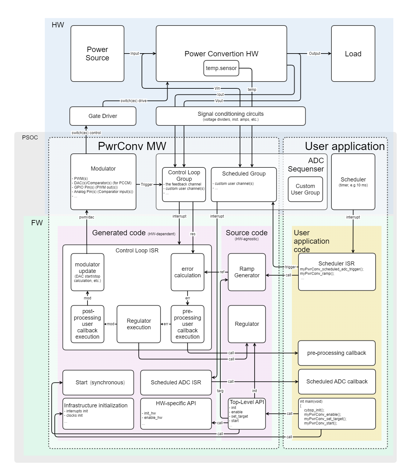
The Power Conversion Middleware consists of the device-agnostic top-level API source code, the power conversion library source code, and the solution personality. The solution personality:
- provides the integration with the Power Conversion Configurator and Device Configurator.
- calculates the regulator coefficients
- generates the power conversion regulator configuration code and device-specific HW configuration code
- generates the control loop ISR
Quick Start
Assume the power converter instance is named in the ModusToolbox™ Device Configurator as 'myPwrConv':
Then, the simplest way to use myPwrConv is to use generated myPwrConv API:
#include "cycfg.h"
void scheduler_callback(void)
{
}
int main(void)
{
init_cycfg_all();
__enable_irq();
Cy_SysTick_Init(CY_SYSTICK_CLOCK_SOURCE_CLK_LF, (uint32_t)(0.01 * 32768));
(void) Cy_SysTick_SetCallback(0UL, scheduler_callback);
Cy_SysTick_Enable();
while (true);
}
void myPwrConv_ramp(void)
Generates the reference ramping for soft start and target changing of the instance.
cy_rslt_t myPwrConv_set_target(float32_t targ)
Applies a new target for Ramp Generator in case of Infineon Control Loop.
cy_rslt_t myPwrConv_get_state(uint32_t mask)
Returns the Power Converter instance current state.
cy_rslt_t myPwrConv_enable(void)
Performs the Power Conversion instance enable sequence:
cy_rslt_t myPwrConv_start(void)
Performs the Power Conversion instance start sequence:
#define MTB_PWRCONV_STATE_RAMP
The ramping flag, indicates that the converter currently is changing the reference value smoothly to ...
Definition: mtb_pwrconv.h:359
- Note
- Not recommended to use in application code any PwrConv FW items (definitions, enums, structures or functions) from static sources or generated files that are not described in this document.
Infineon Control Loop
The whole control loop including the regulator is generated by the personality. The control loop consists of:
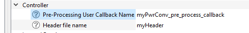
Infineon Control Loop Callbacks
To use the pre- or/and post-process callbacks, the callback itself should be declared in the application level, enable the corresponding feature in the PCC Controller tab:
and the callback name should be passed into the Device Configurator GUI:
To make these callbacks faster, they can be declared as inline functions in header file - in this case the header file name should be also passed into the Device Configurator GUI, as shown above.
And then in the myHeader.h:
__STATIC_INLINE void myPwrConv_pre_process_callback(void)
{
static int32_t error = 0;
error = error / 2 + myPwrConv.ctx->err / 2;
myPwrConv.ctx->err = error;
}
- Note
- For non-inline callbacks there is no need to update the 'Header file name' parameter - it can be left empty (by default).
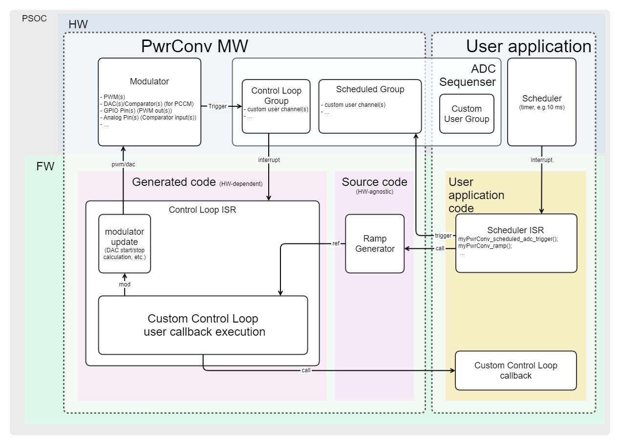
Custom Control Loop
In the Custom Control Loop mode:
- There is no dedicated feedback ADC channel defined in the Control Loop ADC Group - all the channels are equally 'custom'. Therefore, the error mtb_stc_pwrconv_ctx_t::err is not being calculated in the Control Loop ISR (unlike in Infineon Control Loop mode). It is the user's responsibility to define the controlled value(s) and to perform the feedback processing and regulation.
- Because of that, the initial Ramp Generator target value is not pre-calculated, so myPwrConv_set_target has to be called after myPwrConv_init.
- the custom control loop callback is being called instead of the default (based on the selected modulation mode) bult-in regulator with pre-/post-process callbacks in Infineon Control Loop mode.
- the modulator update with the mtb_stc_pwrconv_ctx_t::mod value works exactly like in the Infineon Control Loop mode.
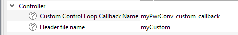
For example, to use the inline custom callback, enter the callback name and the header file name in the Device Configurator:
And then in the myCustom.h:
__STATIC_INLINE void myPwrConv_custom_callback(void)
{
static float32_t modAvg = 0.0;
modAvg = (modAvg < myPwrConv_SLOPE_START_MIN) ? myPwrConv_SLOPE_START_MIN :
(modAvg > myPwrConv_SLOPE_START_MAX) ? myPwrConv_SLOPE_START_MAX : modAvg;
myPwrConv.ctx->mod = (uint32_t)(int32_t)modAvg;
}
__STATIC_FORCEINLINE void myPwrConv_mod_upd(void)
Updates the modulator phase(s) peripheral registers with the mtb_stc_pwrconv_ctx_t::mod value.
__STATIC_FORCEINLINE uint32_t myPwrConv_Vout_get_result(void)
Gets the ADC channel result in raw counts.
__STATIC_FORCEINLINE int32_t myPwrConv_get_error(void)
Returns the error value calculated from reference and feedback values.
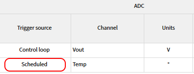
Scheduled ADC Group
To optimize the control loop timing, some ADC measurements can be performed not in the control loop ADC sequencer group, but in the separate scheduled ADC group (configurable in the PCC ADC tab):
which is being periodically triggered by the myPwrConv_scheduled_adc_trigger function. When the scheduled ADC group measurement is done - it rises interrupt which calls the scheduled user callback, which name also should be passed into the Device Configurator GUI:
And implemented in the application code:
void scheduler_callback(void)
{
}
void myPwrConv_scheduled_adc_callback(void)
{
if (myPwrConv_Temp_MAX < myPwrConv_Temp_get_result())
{
}
}
void myPwrConv_scheduled_adc_trigger(void)
Triggers the scheduled ADC group.
cy_rslt_t myPwrConv_disable(void)
Performs the Control System disable (stop) sequence for the Power Conversion instance.
Modulation modes
VCM
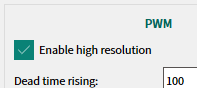
Voltage control modulation mode - the simple PWM, where the pulse width is directly controlled by the 3P3Z regulator (in Infineon Control Loop mode). Supports both high resolution and regular resolution TCPWM modes (configurable in the PCC)
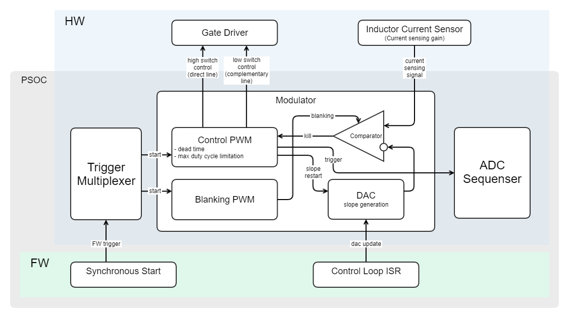
PCCM
Peak-Current control mode is the advanced modulation method which consists of two loops:
- the inner HW inductor current control loop
- the outer FW 2P2Z regulator (in Infineon control loop mode) which controls the PCCM's comparator reference (DAC slope):
Ramp Generator
The PwrConv middleware provides a simple ramp generator - the myPwrConv_ramp function to be called by a periodical event (e.g. some timer ISR/callback, the timing is important to be determined and stable):
#include "cycfg.h"
void scheduler_callback(void)
{
}
int main(void)
{
init_cycfg_all();
__enable_irq();
Cy_SysTick_Init(CY_SYSTICK_CLOCK_SOURCE_CLK_LF, (uint32_t)(0.01 * 32768));
(void) Cy_SysTick_SetCallback(0UL, scheduler_callback);
Cy_SysTick_Enable();
while (true);
}
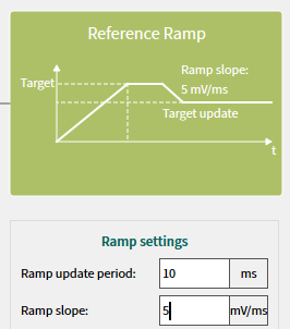
The ramp generator updates the mtb_stc_pwrconv_ctx_t::ref value to always move towards the target value (see myPwrConv_set_target), using the calculated ramp step based on the Ramp update period and Ramp slope parameters configurable in the PCC:
- Note
- It is important to specify the actual time value of myPwrConv_ramp(); calling period in the PCC 'Ramp update period' parameter, shown above.
- Warning
- Bigger Ramp update period and Ramp slope settings shall result in bigger ramp step, so adjust the regulator and ramp scheduling properly.
-
Adjust the Ramp slope to the HW setup: do not make it steeper than the natural speed of capacitor discharging through the load, otherwise, the regulator may fall into saturation with undesired consequences.
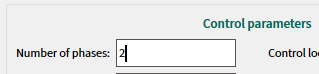
Multi-Phase
The multiple interleaved conversion phases allows to divide a total power between multiple parallel power circuits (switches, inductors) for better heat dissipation, reliability, and power density of the converter. Also, in terms of EMC the multi-phasing method lowers magnitude and spreads the spectrum of both the electromagnetic emissions and the voltage/current ripples on power lines. The PwrConv Buck topology allow up to 4 phases (in both VCM and PCCM modes) controlled by the same FW regulator (configurable in the PCC)
- Note
- The output capacitor and output current display on the PCC schematic as common for all the phases, so the entered C, Cesr and Iout values also should be common - the resulting capacitance and Cesr of all in-parallel-connected capacitors (if any), and the resulting current (sum so all the phase currents).
The inductor is shown separately for each phase, so the L and Lesr values should be specified for single inductor.
DMA usage
The DMA HW blocks can be used to reduce the Control Loop ISR timing.
ADC DMA
There is a possibility to arrange a DMA transfer from the ADC result register to RAM cell for each Control Loop ADC channel separately depending whether this channel data will be used in the Control Loop FW (callbacks) or for Hardware Protection only. This feature reduces the Control Loop execution by a number of CPU cycles needed to get data from the peripheral register.
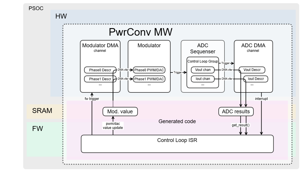
Modulator DMA
The data transfer from mtb_stc_pwrconv_ctx_t::mod to the modulator (PWM/DAC) peripheral registers, this is primarily reasonable to use with Multi-Phase and PCCM modes, where to update more than one peripheral modulator register.
- Note
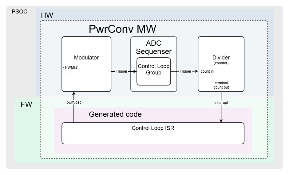
- For the Control Loop Frequency Divider usage the ADC DMA triggers the Divider and the Divider generates the Control Loop interrupt request.
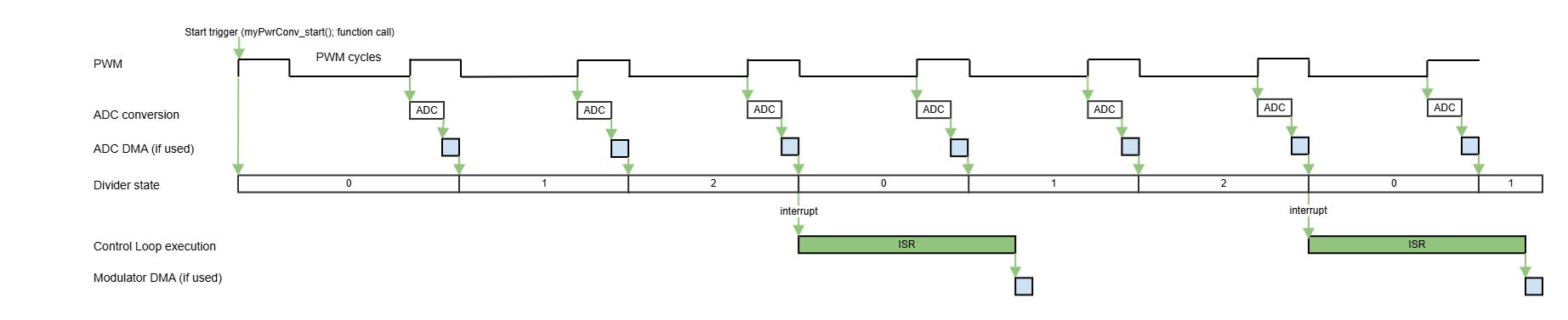
Control Loop Frequency Divider
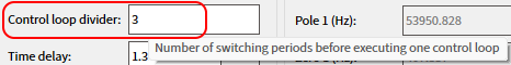
For high PWM switching frequencies and heavy control loops, when there might be not enough time to execute the control loop code within a single PWM period, the Control Loop Frequency Divider can be used, which is a HW counter for ADC (or DMA) triggers and produces Control Loop interrupt requests once per 2..5 PWM cycles.
For example, the PCC configuration:
Then interrupt shall appear on each 3rd PWM cycle:
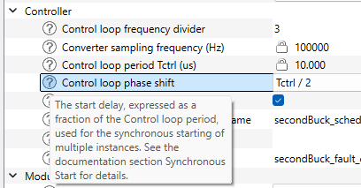
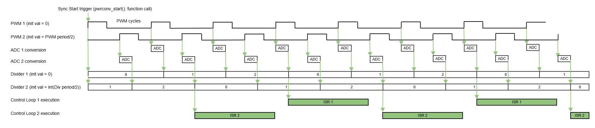
Synchronous Start
For multiple instances with the same Control Loop periods, they may be started simultaneously with a specified control loop phase shift, to avoid the control loop ISR execution overlapping. In this case, use the 'Control loop phase shift' parameter:
in conjunction with a generated pwrconv_start() function (common for all the instances) instead of regular instance-based [instance_name]_start() functions:
cy_rslt_t pwrconv_start(void)
Starts all the Power Conversion instances in the project synchronously.
For the Control Loop Frequency Divider usage, this phase shift value is distributed between the PWM initial counter and the Divider initial counter values, so that the entire Control Loop period is taking into account. For example, for two instances, with the same Fsw and Control Loop divider is 3, and the second 'Control loop phase shift' is Tctrl/2, the phase shift is 1.5 PWM cycle, so the fractional part (0.5) belongs to the PWM itself, and the integer part (1.0) belongs to the Divider initial value:
Hardware Protection
The ADC Limit Crossing Detection HW blocks are involved to perform the automatic HW protection of the power converter configurable for each ADC channel in the PCC:
- Note
- The protection blocks are configured in the PCC, and the API functions to control them at run time are generated: myPwrConv_prot_enable, myPwrConv_prot_disable. However they are not automatically enabled at the starting, because some of them (e.g. Vout under-voltage) may be triggered during soft start, so it is user's responsibility to enable a configured protection for each channel at run time (e.g. after the soft start rump up finished for the Vout channel).
Then, when the appropriate protection block is enabled and the measured voltage crosses the ADC Limit Crossing Detection threshold, the power converter PWM(s) (including blanking for PCCM and all multiphase phases) are killed by HW trigger signal from ADC. At the same time, a protection interrupt occurs, the converter is disabled by FW, and the fault callback is called, so the fault event can be processed by application FW:
void scheduler_callback(void)
{
{
}
}
uint32_t protStatus = 0UL;
void myPwrConv_fault_callback(void)
{
}
__STATIC_INLINE uint32_t myPwrConv_prot_get_status(void)
Returns the HW protection status for all PwrConv ADC channels.
__STATIC_INLINE void myPwrConv_Vout_prot_enable(void)
Enables HW protection for PwrConv ADC channel.
#define MTB_PWRCONV_STATE_RUN
The running flag, indicates that the converter is currently running.
Definition: mtb_pwrconv.h:356
if (0UL != (myPwrConv_Vout_MSK & protStatus))
{
protStatus &= ~myPwrConv_Vout_MSK;
}
Cy_HPPASS_SAR_Limit_Config(myPwrConv_Vout_limit_IDX, &myPwrConv_Vout_limit_cfg);
__STATIC_INLINE uint32_t myPwrConv_Vout_units_to_counts(float32_t units)
Calculates the value in ADC counts from the value in the channel natural units (Volts/Amperes/etc....
- Warning
- Each feature like PCCM, Multi-Phase, ADC DMA, Control Loop Frequency Divider, Hardware Protection makes the trigger signals routing more complicated, and combination of these features may cause the trigger routing/multiplexing resources over-usage depending on the device capabilities.
Changelog