|
CAT2 Peripheral Driver Library
|
|
CAT2 Peripheral Driver Library
|
The I2S driver provides a function API to manage Inter-IC Sound. More...
Modules | |
| Macros | |
| Functions | |
| Data Structures | |
| Enumerated Types | |
The I2S driver provides a function API to manage Inter-IC Sound.
The functions and other declarations used in this driver are in cy_i2s.h. You can include cy_pdl.h to get access to all functions and declarations in the PDL.
I2S is used to send digital audio streaming data to external I2S devices, such as audio codecs or simple DACs.
Features:
The I2S bus is an industry standard. The hardware interface was developed by Philips Semiconductors (now NXP Semiconductors).
To set up an I2S, provide the configuration parameters in the cy_stc_i2s_config_t structure. To initialize the I2S block, call the Cy_I2S_Init function, providing the filled cy_stc_i2s_config_t structure. Before starting the transmission, clear the FIFO Cy_I2S_ClearTxFifo, then fill the first Tx data frame by calling Cy_I2S_WriteTxData once for each channel (e.g. twice for I2S mode with only two channels) with zero data. Then call the Cy_I2S_EnableTx itself.
Example code:
For example, if the trigger interrupt is used during operation, the ISR should call the Cy_I2S_WriteTxData as many times as required for your FIFO payload, but not more than the FIFO size. Then call Cy_I2S_ClearInterrupt with appropriate parameters.
The I2S/Left Justified data formats always contains two data channels. They are ordered one-by-one in the FIFOs and left always goes first. So in case of mono audio stream transmission, each sample can be put twice into the TX FIFO (in this case both channels will sound the same), or combined with zeroes: sample1-zero-sample2-zero (in this case only the left channel will finally sound, for a right-only case, zero should go first). The TDM frame word order in FIFOs is similar, one-by-one.
The I2S frame appears as:
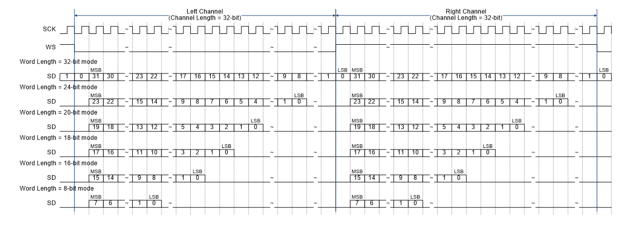
This is an example for the channel length = 32. A similar case exists for the rest channel lengths, with one limitation: the word length could be less than or equal to the channel length. See the device technical reference manual (TRM) for more details.
The internal clock source for I2S is one of the Peripheral Clock Dividers. I2S can accept an external interface clock through the clk_if terminal, which can be connected to the dedicated GPIO pin only. I2S clock source (either an external or internal) is divided by a common configurable I2S Clock divider and then by a constant 8x divider. The resulting clock at the output of these dividers is the actual bit clock of the I2S bus stream:
Bit Rate (kbps) = I2S Clock / I2S Clock divider / 8
The actual frame rate can be calculated from the bit rate divided by the frame length (channel length x number of channels). For I2S/Left Justified modes the number of channels is always 2:
Frame Rate (ksps) = Bit Rate (kbps) / Channel length / 2
For TDM modes, the Frame Length is always 256-bit clocks, so the Frame Rate expression is simplified:
Frame Rate (ksps) = Bit Rate (kbps) / 256
| Version | Changes | Reason for Change |
|---|---|---|
| 1.10 | The Cy_I2S_DeepSleepCallback parameter type is changed to match with the cy_stc_syspm_callback_t::callback type. | Eliminate compiler warnings |
| 1.0.1 | Update the paths to the code snippets. | PDL structure update. |
| 1.0 | Initial version |