 |
MTB CAT1 Peripheral driver library
|
|
MTB CAT1 Peripheral driver library
|
The LIN driver provides a function API to manage Local Interconnect Network.
The functions and other declarations used in this driver are in cy_lin.h. You can include cy_pdl.h to get access to all functions and declarations in the PDL.
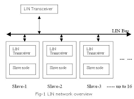
The Local Interconnect Network (LIN) bus was developed to create a standard for low-cost, low-end multiplexed communication. The use of a standard bus protocol promotes the interoperability of network nodes. The LIN bus is a sub-bus system based on a serial communications protocol. The bus is a single master / multiple slave bus that uses a single wire to transmit data. A LIN cluster exchanges messages with a pre-defined message frame format. The master node initiates a message exchange. Both the master node and the slave nodes can transmit (TX) and receive (RX). The LIN protocol is half-duplex: a LIN node is either transmitting or receiving, but it cannot transmit and receive at the same time. Messages are exchanged when the LIN cluster is in operational mode. A LIN cluster also exchanges wake-up signals. Both the master node and the slave nodes can initiate a wake-up. Wake-up signals are exchanged when the LIN cluster is in sleep mode. The LIN bus can have a length of 10's of meters and has a bit-rate in the range of 1 kbps to 20 kbps. Most bus timing is expressed in bit periods (e.g. a 20 kbps LIN bus has a 50 us bit period). The LIN bus uses single wire communication using a "lin" line with an operating Voltage of 12 V. Most master and slave nodes use discrete transceiver devices.
Features:
Per LIN channel:
The LIN bus is an industry standard.
Message Format:
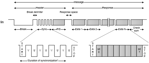
A LIN message have a pre-defined message frame format.
A frame consists of a header, followed by a response. A frame header consists of a break field, followed by a synchronization field, followed by a protected identifier (PID) field. A frame response consists of 1, 2, ..., or 8 data fields, followed by a checksum field. The PID field, data fields and checksum fields are supported through a message buffer registers (MMIO PID_CHECKSUM, DATA0 and DATA1 registers).
When transmitting, the message buffer registers provides the "to be transmitted" field values (with the exception of the checksum field, which is dynamically calculated). When receiving, the message buffer registers capture the received field values.
The break field length and the break delimiter length.
All other fields are 8-bit (1Byte) values that are transferred in a "UART format" with 1 START bit period and 1 STOP bit period.
When receiving, the START and STOP bits are verified. In case of verification failure, a RX_HEADER_FRAME_ERROR or RX_RESPONSE_FRAME_ERROR is activated. Byte values are transmitted with least significant bit first format.
Initialization:
The LIN initialization is according to the Options setup in the passed Config Struct. cy_stc_lin_config_t Several validations are done before that and an error is returned if invalid Modes are requested.
Lin Configuration:
Break_Wakup_Length field is used for transmission/reception of BOTH break and wakeup signals.
Command:
There are 5 commands that user can set in combinations. to send the data.
The following restrictions apply when programming the commands:
The break or wakeup detection is always enabled, regardless of CMD register setting.
Following are the combination of commands that user can use. These commands can be provided as predefined commands in cy_lin.h.
Interrupt Handling :
Lin channels have dedicated interrupts
Driver does not handle interrupts and it is user's responsibility to clear interrupts. User registers for the list of interrupts given below and handle the interrupts in the interrupt handler. A code snippet is given below for registering to the interrupts and handling the interrupts in interrupt handler.
There are 16 type of interrupts that the software can register for
| Version | Changes | Reason for Change |
|---|---|---|
| 1.2 | Sets LIN break/wakeup field length updated in the Cy_LIN_SetBreakWakeupFieldLength function | Bug fix |
| Sets LIN response field data length updated in the Cy_LIN_SetDataLength function | Bug fix | |
| Sets LIN checksum type setting updated in the Cy_LIN_SetChecksumType function | Bug fix | |
| 1.1 | Fixed MISRA 2012 violations. | MISRA 2012 compliance. |
| 1.0 | Initial version |
API Reference | |
| Macros | |
| Functions | |
| Data Structures | |
| Enumerated Types | |