 |
LIN Middleware 2.0.0.1261
|

|
|
LIN Middleware 2.0.0.1261
|
|
LIN middleware implements LIN 2.2 Slave node for PSOC 4 devices. Options for ISO 17987 compliance are also available. The LIN Configurator and Device Configurator facilitate configuring the middleware.
Features:
Include mtb_lin.h to get access to all the functions and other declarations in this middleware.
The middleware uses the SCB UART hardware with built-in LIN support to implement the physical layer.
See the Quick Start Guide to start using the middleware.
The Configuration Considerations section provides guidance on configuration and initialization of the middleware.
Refer to the Specification Conformance section for the API deviation from the specification.
The below steps describe the simplest way of enabling the LIN Slave.
Launch ModusToolbox Library Manager and enable the LIN middleware. This step is required only if the ModusToolbox IDE is used. Otherwise, ensure the LIN Middleware is included in your project.
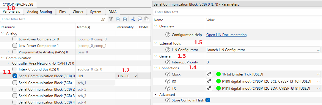
See the Device Configurator section for details.
Launch the LIN Configurator from the Device Configurator (see STEP 2, item 5) or as a standalone tool from the ModusToolbox Quick Panel. Configure the parameters on the General, Frames, Signals, Transport Layer and Configuration Services tabs per your application requirements. Refer to the LIN Configurator User Guide (see More Information) for detailed instructions.
See the LIN Configurator section for details.
The following code snippet shows the LIN initialization:
See the Initialization section for details.
Use a supported PSOC 4 development kit together with the CY8CKIT-026 CAN and LIN Shield Kit, which provides the LIN transceiver hardware.
Connect the device to the LIN Master. Configure LIN Master to send frames and observe updated signals in the LIN Slave application.
The configuration workflow follows the steps described in Quick Start Guide. The subsections below provide additional details on each stage.
The list of sections under Configuration Considerations:
The Device Configurator generates the hardware-level configuration for the LIN-SCB block, which includes:
The LIN Configurator generates the mtb_stc_lin_config_t structure instance in mtbcfg_lin.h and mtbcfg_lin.c files. This structure is passed to l_sys_init().
The initialization must follow the strict order:
The middleware requires two user-implemented interrupt handlers, passed to l_sys_init():
This section describes the deviations from the API defined by the LIN specifications.
This section describes the differences between PSOC Creator LIN component and the LIN middleware API.
| # | PSOC Creator LIN component | LIN middleware |
|---|---|---|
| 1 | The result of the MTB_LIN_IOCTL_READ_STATUS operation of the l_ifc_ioctl() is returned by the function. | The result of the MTB_LIN_IOCTL_READ_STATUS operation of the l_ifc_ioctl() is returned via the pointer specified by the pv parameter. The function returns MTB_LIN_STATUS_SUCCESS. |
| 2 | No l_sys_irq_disable() and l_sys_irq_restore() implemented. | Added implementation of the l_sys_irq_disable() and l_sys_irq_restore(). |
| 3 | All the interrupt service routines are initialized inside of the component - no any actions required on the application level. | The communication and inactivity interrupt service routines should be implemented on the application level. Refer to the STEP 4: Update main.c section for the more details. |
This section describes MISRA-C:2012 compliance and deviations for the LIN.
MISRA stands for Motor Industry Software Reliability Association. The MISRA specification covers a set of 10 mandatory rules, 110 required rules and 39 advisory rules that apply to the firmware design and has been put together by the Automotive Industry to enhance the quality and robustness of the firmware code embedded in automotive devices.
The MISRA specification defines two categories of deviations (see section 5.4 of the MISRA-C:2012 specification):
Project Deviations are documented in the current section below.
Specific deviations are documented in the source code, close to the deviation occurrence. For each deviation, a special macro identifies the relevant rule or directive number, and reason.
This section provides a MISRA compliance analysis environment description.
| Component | Name | Version |
|---|---|---|
| Test Specification | MISRA-C:2012 Guidelines for the use of the C language in critical systems | March 2013 |
| MISRA Checking Tool | Coverity Static Analysis Tool | 2022.12.0 |
The table below provides the list of deviated required rules. Advisory rules deviation is not documented because it is not required per MISRA specification.
| Rule ID | Rule Description | Description of Deviation(s) |
|---|---|---|
| Rule 3.1 | The character sequences /* and // shall not be used within a comment. | Usage of special comment symbols is needed for Doxygen comment support, it does not have any impact. |
| Rule 5.8 | Identifiers that define objects or functions with external linkage shall be unique. | During the code analysis, the same source files are compiled multiple times with device-specific options. All object and function identifiers are unique for each specific run. |
| Version | Changes | Reason for Change |
|---|---|---|
| 2.0 | Removed CAT2 Hardware Abstraction Layers (mtb-hal-cat2) 2.x support. Added support for new PSOC™ 4000T device family. Added a new LIN personality. Added mtb_stc_lin_ifc_config_t structure. Updated l_ifc_init() and l_sys_init() API interfaces. Updated mtb_stc_lin_context_t structure. | Support new device families. |
| 1.10 | Added CAT2 Hardware Abstraction Layers (mtb-hal-cat2) 2.x support. | |
| 1.0 | Initial Version |
For more information, refer to the following documents: