Overview
The purpose of the DFU middleware library is to provide an SDK for updating firmware images. The middleware allows creating these types of projects:
- The application loader receives an image and programs it into memory.
- A loadable application is transferred and programmed.
A project can contain the features of both types.
General Description
Include cy_dfu.h to get access to all functions and other declarations in this library.
The DFU SDK has the following features:
- Reads firmware images from a host through a number of transport interfaces, e.g. USB, UART, I2C, SPI, CANFD
- Supports dynamic switching (during runtime) of the communication interfaces
- Provides ready-for-use transport interface templates based on HAL/PDL drivers for PSOC Control C3 and PSE84 devices
- Supported flow: MCUBoot compatibility
- Device support: PSOC Control C3 and PSE84
- Programs a firmware image to the specified address in internal flash, XIP region or any external memory that supports the DFU API
- Validates applications
- Supports encrypted image files - transfers encrypted images without decrypting in the middle
- Supports customization
- Supports the CRC-32 checksum to validate data.
- Supports extend of the host command/response protocol with custom commands.
Quick Start Guide
DFU Transport (MCUBoot compatible) flow
See the AN235935 - Getting started with PSOC™ Edge E84 on ModusToolbox™ software for more details on the PSOC™ Edge E84 MCU and MCUBoot.
Description
The DFU supports the usage of the MCUBoot as a bootloader and provides a transport layer for transferring a new application image to the slot. Set macro CY_DFU_FLOW to CY_DFU_MCUBOOT_FLOW to enable this flow.
STEP1: Projects preparation.
Create a ModusToolbox™ application for the PSOC Control C3 or PSE84 devices.
For example:
- the KIT_PSC3M5_EVK can be used for PSOC Control C3 device;
- the KIT_PSE84_EVAL_EPC2 can be used for PSE84 device.
Create a new application in the ModusToolbox™ IDE using an appropriate BSP and an empty application as a template (Empty App). Name it "DFU_App0". For details, refer to the ModusToolbox™ 3.x IDE Quick Start Guide.
- Note
- The ModusToolbox™ PSOC Edge Protect Bootloader application must be used as a base project for the KIT_PSE84_EVAL_EPC2 and the KIT_PSC3M5_EVK application loader. Please refer to the project documentation for set-up and configuration.
- Include the DFU middleware into the project using the ModusToolbox™ Library Manager.
- Add the DFU transport components to project's Makefile to enable the transport interface(s). In our case, I2C is used:
- Update project's Makefile to use MCUBoot flow:
- To download an image to the external memory, add the next defines to the project's Makefile:
DEFINES += CY_FLASH_SIZEOF_ROW=0x100
- Note
- The application base address and size must be set in accordance with memory layout in the project.
DEFINES += CY_DFU_APP_ADDRESS=0x70380000
DEFINES += CY_DFU_APP_SIZE=0x10000
STEP2: Add DFU logic to main.c
- Include the required headers.
#include "cy_dfu.h"
#include "cy_dfu_logging.h"
- Initialize the variables and call the DFU initialization function:
static const uint32_t paramsTimeout = 20U;
- Call the DFU initialization function
{
CY_DFU_LOG_ERR("DFU initialization is failed");
CY_ASSERT(0U);
}
- Initialize the DFU transport layer. Refer to the Firmware Update via I2C section.
- For a device with external memory (for example PSE84), initialize the serial-memory middleware and provide a pointer to the serial-memory object for DFU.
cy_rslt_t result;
result = mtb_serial_memory_setup(&dfuExtMemObj, MTB_SERIAL_MEMORY_CHIP_SELECT_1,
DFU_EXT_MEM_HW, &DFU_EXT_MEM_hal_clock,
&smifMemContext, &smifMemInfo, &smif0BlockConfig);
if (CY_RSLT_SUCCESS != result)
{
CY_DFU_LOG_ERR("mtb_serial_memory_setup returns error status: %lX", (uint32_t)result);
}
- Note
- Configure the SMIF HW resource in the Device Configurator. In this example, the DFU_EXT_MEM alias is used.
- Start the I2C transport
- Update the main loop with the Host Command/Response protocol processing:
uint32_t count = 0U;
for (;;)
{
++count;
{
{
CY_DFU_LOG_INF("The application image is successfully loaded");
break;
}
{
CY_DFU_LOG_ERR("Error during application verifying");
}
}
{
CY_DFU_LOG_ERR("Error during loading process");
}
{
{
count = 0U;
}
{
if (count >= (DFU_HOST_CMD_TIMEOUT_MS/paramsTimeout))
{
CY_DFU_LOG_ERR("Timeout error");
count = 0U;
}
}
else
{
CY_DFU_LOG_ERR("Error during updating state 0x%X", (unsigned int)dfuStatus);
count = 0U;
(void) mtb_hal_system_delay_ms(paramsTimeout);
}
}
}
- Warning
- The DFU main routine provided in the snippet above, must be placed before start the firmware images detected by the PSOC Edge Protect Bootloader, just before following line in the main.c:
BOOT_LOG_INF("boot_go_for_image_id");
- Note
- To use DFU logging, initialize the retarget-io middleware
STEP3: Build and Program Loader Application
Connect your kit to the computer. Build and program the device.
- Note
- The CY_DFU_PRODUCT warning displays if default values are used and they need to be changed. CY_DFU_PRODUCT can be defined in the Makefile.
STEP4: Create a loadable application (Application 1).
- Create a ModusToolbox™ application for the same devices as in STEP1. Use an empty application as a template (Empty App). Name it "DFU_App1".
- Note
- For creation of the loadable application for KIT_PSE84_EVAL_EPC2, refer to the PSOC Edge Protect Bootloader documentation.
- Update the project post build steps to generate HEX files with an offset to the memory region of the loadable application.
- Added Makefile variables for generating the HEX file.
BINARY_PATH=./build/$(TARGET)/$(CONFIG)/$(APPNAME)
HEX_TOOL=$(MTB_TOOLCHAIN_GCC_ARM__BASE_DIR)/bin/arm-none-eabi-objcopy
HEX_TOOL_OPTIONS=-O ihex
APP_OFFSET=0x00030000
- Add a post build step to put the loadable application at the upgradable area offset
# Custom post-build commands to run.
POSTBUILD=\
cp -f $(BINARY_PATH).hex $(BINARY_PATH)_raw.hex;\
rm -f $(BINARY_PATH).hex;\
$(HEX_TOOL) --change-addresses=$(APP_OFFSET) $(HEX_TOOL_OPTIONS) $(BINARY_PATH).elf $(BINARY_PATH).hex;
- Load the application to the device using the DFU Host Tool. Refer to the DFU Host Tool user guide for the details of using the HEX file as an input.
- Note
- Only DFU Host Tool v2.0 or later support the HEX file as an input.
Design Considerations
Supported transports:
| Devices | I2C (HAL-Next) | UART (HAL-Next) | SPI (HAL-Next) | CANFD (PDL) | USB: CDC and HID (emUSB-Device middleware) |
| PSOC Control C3 | Supported | Supported | Supported | Supported | Not Supported |
| PSE84 | Supported | Supported | Supported | Not Supported | Supported |
Firmware Update via transports based on HAL-Next
The next transports support HAL-Next flow:
To configure transport based on HAL-Next flow:
- Add to COMPONENTS varialbe in the Makefile DFU_<transport name> (Example: DFU_UART, DFU_I2C, etc)
- Configure the communication protocol in Device Configurator. The Device Configurator will generate appropriate configuration structures and macro for the protocol initialization by PDL and HAL APIs. The DFU middleware does not re-configure any protocol settings like baudrate, data width, address, etc.
- Configure the HW using PDL initialization APIs. For some transport, configure the interrupt too.
- Setup HAL driver by appropriate HAL APIs
- Create the DFU transport callback function. Typically, this function enables or disables HW by PDL APIs. For some cases, this function makes full HW initialization instead of only enabling/disabling. This callback will be automatically called by DFU middleware during the protocol selection.
- Create transport DFU initialization structure. This structure has pointers to the HAL driver object and DFU transport callback.
- Note
- Check the next subsections for code snippets with transports configuration
Dynamic switching for DFU transports
The DFU middleware supports dynamic switching of configured transports. This can be achieved by calling the Cy_DFU_TransportStart() function with a new type of transport. Typically, on the supported device, the SPI, UART and I2C protocols use the same pins and are implemented on the same HW block. The Device Configurator supports only one configuration for one instance of HW block. This complicates the application design if the dynamic switching of the SPI, UART and I2C protocols is required and for these protocols, the same HW IP block and the same pins are used. For this case, for HW resource in the user application, create separate configurations for each transport including pins and clocks - at least, peripheral clock dividers. Also, the user application must ensure that the HW resources required for transport operation are reserved including SCB, pins, clock dividers and others.
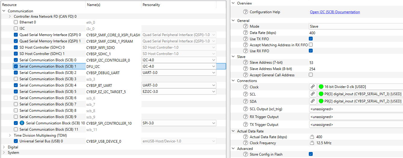
Firmware Update via I2C
The I2C specific configuration options:
- The size of the buffer for sending and receiving data is configured by macro. By default the 128 bytes are selected but the size can be re-configured in the Makefile. Add DFU_I2C_TX_BUFFER_SIZE and DFU_I2C_RX_BUFFER_SIZE to the define variable and assign new values:
DEFINES+=DFU_I2C_TX_BUFFER_SIZE=64 DFU_I2C_RX_BUFFER_SIZE=64
- The I2C transport requires configured interrupt routine
- To add transport to build, add DFU_I2C to COMPONENTS variable in the Makefile:
To set up the I2C personality in the ModusToolbox™ Device Configurator for the I2C DFU transport for PSE84 MCU, see the screenshot below.
Serial Communication Block, Parameters - set the personality alias and I2C mode for the alternate serial interface:
| Parameter name | Value |
| Personality alias name | DFU_I2C |
| Mode | Slave |
| Data rate (kbps) | 400 |
| Use TX/RX FIFOs | Enabled |
| Slave Address (7-bit) | 53 |
| Clock | Set according to data bitrate setting |
| SCL | P9.3 |
| SDA | P9.2 |
The Example of I2C transport configuration:
- Include the required header files:
- PDL/HAL drivers specific headers
- cybsp.h - to use generated code from the Device Configurator
- DFU core and transport headers.
#include "transport_i2c.h"
#include "cy_dfu.h"
#include "cy_dfu_logging.h"
#include "mtb_hal_i2c.h"
#include "cy_scb_i2c.h"
#include "cy_sysint.h"
#include "cybsp.h"
- Define the global variables - first is the HAL driver object to be provided to transport and the second is PDL driver context.
static mtb_hal_i2c_t dfuI2cHalObj;
static cy_stc_scb_i2c_context_t dfuI2cContext;
- Create interrupt handler for I2C HW
void dfuI2cIsr(void)
{
mtb_hal_i2c_process_interrupt(&dfuI2cHalObj);
}
- Create I2C transport callback
void dfuI2cTransportCallback(cy_en_dfu_transport_i2c_action_t action)
{
if (action == CY_DFU_TRANSPORT_I2C_INIT)
{
Cy_SCB_I2C_Enable(DFU_I2C_HW);
CY_DFU_LOG_INF("I2C transport is enabled");
}
else if (action == CY_DFU_TRANSPORT_I2C_DEINIT)
{
Cy_SCB_I2C_Disable(DFU_I2C_HW, &dfuI2cContext);
CY_DFU_LOG_INF("I2C transport is disabled");
}
}
- Configure I2C HW using PDL initialization APIs, then set up the HAL driver and configure the I2C interrupt
cy_en_scb_i2c_status_t pdlI2cStatus;
cy_en_sysint_status_t pdlSysIntStatus;
cy_rslt_t halStatus;
pdlI2cStatus = Cy_SCB_I2C_Init(DFU_I2C_HW, &DFU_I2C_config, &dfuI2cContext);
if (CY_SCB_I2C_SUCCESS != pdlI2cStatus)
{
CY_DFU_LOG_ERR("Error during I2C PDL initialization. Status: %X", pdlI2cStatus);
}
else
{
halStatus = mtb_hal_i2c_setup(&dfuI2cHalObj, &DFU_I2C_hal_config, &dfuI2cContext, NULL);
if (CY_RSLT_SUCCESS != halStatus)
{
CY_DFU_LOG_ERR("Error during I2C HAL initialization. Status: %lX", halStatus);
}
else
{
cy_stc_sysint_t i2cIsrCfg =
{
.intrSrc = DFU_I2C_IRQ,
.intrPriority = 3U
};
pdlSysIntStatus = Cy_SysInt_Init(&i2cIsrCfg, dfuI2cIsr);
if (CY_SYSINT_SUCCESS != pdlSysIntStatus)
{
CY_DFU_LOG_ERR("Error during I2C Interrupt initialization. Status: %X", pdlSysIntStatus);
}
else
{
NVIC_EnableIRQ((IRQn_Type) i2cIsrCfg.intrSrc);
CY_DFU_LOG_INF("I2C transport is initialized");
}
}
}
cy_stc_dfu_transport_i2c_cfg_t i2cTransportCfg =
{
.i2c = &dfuI2cHalObj,
.callback = dfuI2cTransportCallback,
};
Cy_DFU_TransportI2cConfig(&i2cTransportCfg);
Firmware Update via UART
The UART specific configuration options:
- To add transport to the build, add the DFU_UART to COMPONENTS variable in the Makefile:
The Example of UART transport configuration:
- Include the required header files:
- cybsp.h to use generated code from the Device Configurator
- cybsp.h to use generated code from Device-Configurator
- DFU core and transport headers.
#include "transport_uart.h"
#include "cy_dfu.h"
#include "cy_dfu_logging.h"
#include "mtb_hal_uart.h"
#include "cy_scb_uart.h"
#include "cybsp.h"
- Define the global variables - first is the HAL driver object to be provided to transport and the second is PDL driver context.
static mtb_hal_uart_t dfuUartHalObj;
static cy_stc_scb_uart_context_t dfuUartContext;
- Create UART transport callback
void dfuUartTransportCallback(cy_en_dfu_transport_uart_action_t action)
{
if (action == CY_DFU_TRANSPORT_UART_INIT)
{
Cy_SCB_UART_Enable(DFU_UART_HW);
CY_DFU_LOG_INF("UART transport is enabled");
}
else if (action == CY_DFU_TRANSPORT_UART_DEINIT)
{
Cy_SCB_UART_Disable(DFU_UART_HW, &dfuUartContext);
CY_DFU_LOG_INF("UART transport is disabled");
}
}
- Configure UART HW using PDL initialization APIs, then set up the HAL driver and configure the UART interrupt
cy_en_scb_uart_status_t pdlUartStatus;
cy_rslt_t halStatus;
pdlUartStatus = Cy_SCB_UART_Init(DFU_UART_HW, &DFU_UART_config, &dfuUartContext);
if (CY_SCB_UART_SUCCESS != pdlUartStatus)
{
CY_DFU_LOG_ERR("Error during UART PDL initialization. Status: %X", pdlUartStatus);
}
else
{
halStatus = mtb_hal_uart_setup(&dfuUartHalObj, &DFU_UART_hal_config, &dfuUartContext, NULL);
if (CY_RSLT_SUCCESS != halStatus)
{
CY_DFU_LOG_ERR("Error during UART HAL initialization. Status: %lX", halStatus);
}
else
{
CY_DFU_LOG_INF("UART transport is initialized");
}
}
cy_stc_dfu_transport_uart_cfg_t uartTransportCfg =
{
.uart = &dfuUartHalObj,
.callback = dfuUartTransportCallback,
};
Cy_DFU_TransportUartConfig(&uartTransportCfg);
- Note
- Select the UART HW and configure it in the Device Configurator, write the next name for the DFU_UART example.
Firmware Update via SPI
The SPI specific configuration options:
- The SPI transport requires configured interrupt routine
- To add transport to the build, add the DFU_SPI to COMPONENTS variable in the Makefile:
The Example of SPI transport configuration:
- Include the required header files:
- PDL/HAL drivers specific headers
- cybsp.h to use generated code from the Device Configurator
- DFU core and transport headers.
#include "transport_spi.h"
#include "cy_dfu.h"
#include "cy_dfu_logging.h"
#include "mtb_hal_spi.h"
#include "cy_scb_spi.h"
#include "cy_sysint.h"
#include "cybsp.h"
- Define the global variables - first is the HAL driver object to be provided to transport and the second is PDL driver context.
static mtb_hal_spi_t dfuSpiHalObj;
static cy_stc_scb_spi_context_t dfuSpiContext;
- Create interrupt handler for SPI HW
void dfuSpiIsr(void)
{
mtb_hal_spi_process_interrupt(&dfuSpiHalObj);
}
- Create SPI transport callback
void dfuSpiTransportCallback(cy_en_dfu_transport_spi_action_t action)
{
if (action == CY_DFU_TRANSPORT_SPI_INIT)
{
Cy_SCB_SPI_Enable(DFU_SPI_HW);
CY_DFU_LOG_INF("SPI transport is enabled");
}
else if (action == CY_DFU_TRANSPORT_SPI_DEINIT)
{
Cy_SCB_SPI_Disable(DFU_SPI_HW, &dfuSpiContext);
CY_DFU_LOG_INF("SPI transport is disabled");
}
}
- Configure SPI HW using PDL initialization APIs, then set up the HAL driver and configure the SPI interrupt
cy_en_scb_spi_status_t pdlSpiStatus;
cy_en_sysint_status_t pdlSysIntStatus;
cy_rslt_t halStatus;
pdlSpiStatus = Cy_SCB_SPI_Init(DFU_SPI_HW, &DFU_SPI_config, &dfuSpiContext);
if (CY_SCB_SPI_SUCCESS != pdlSpiStatus)
{
CY_DFU_LOG_ERR("Error during SPI PDL initialization. Status: %X", pdlSpiStatus);
}
else
{
halStatus = mtb_hal_spi_setup(&dfuSpiHalObj, &DFU_SPI_hal_config, &dfuSpiContext, NULL);
if (CY_RSLT_SUCCESS != halStatus)
{
CY_DFU_LOG_ERR("Error during SPI HAL initialization. Status: %lX", halStatus);
}
else
{
dfuSpiHalObj.is_target = true;
cy_stc_sysint_t spiIsrCfg =
{
.intrSrc = DFU_SPI_IRQ,
.intrPriority = 3U
};
pdlSysIntStatus = Cy_SysInt_Init(&spiIsrCfg, dfuSpiIsr);
if (CY_SYSINT_SUCCESS != pdlSysIntStatus)
{
CY_DFU_LOG_ERR("Error during SPI Interrupt initialization. Status: %X", pdlSysIntStatus);
}
else
{
NVIC_EnableIRQ((IRQn_Type) spiIsrCfg.intrSrc);
CY_DFU_LOG_INF("SPI transport is initialized");
}
}
}
cy_stc_dfu_transport_spi_cfg_t spiTransportCfg =
{
.spi = &dfuSpiHalObj,
.callback = dfuSpiTransportCallback,
};
Cy_DFU_TransportSpiConfig(&spiTransportCfg);
- Note
- Select the SPI HW and configure it in the Device Configurator, write the next name for the DFU_SPI example.
Firmware Update via emUSB CDC and HID transports
The CDC and HID transports are based on emUSB-Device middleware . The configuration of USB for the DFU middleware is similar to a standard use case, but the configuration steps are divided into those implemented in transport and the other to be done in the user application.
As the emUSB-Device middleware supports the composite device feature, the transports are designed to not reserve the whole USB only for the DFU middleware purpose. Also, both the CDC and HID transports can be configured together: both interfaces can be visible and ready to transmit data. But only one interface can be used for communication at the same time. To select the required transport, call Cy_DFU_TransportStart.
To use the CDC or HID transports, add the corresponding components to project's Makefile:
- For CDC:
COMPONENTS+=DFU_EMUSB_CDC
- For HID:
COMPONENTS+=DFU_EMUSB_HID
- Note
- Also, update the components with USBD_BASE:
-
Typically, the emUSB-Device middleware is not added to your project automatically, so add it manually by the Library Manager.
CDC transport configuration
- Include the required header files:
#include "transport_emusb_cdc.h"
#include "cy_dfu.h"
#include "cy_dfu_logging.h"
#include "USB.h"
- Add USB Device Info structure
static const USB_DEVICE_INFO deviceInfo =
{
0x058B,
0xF21D,
"Infineon",
"DFU USB CDC Transport",
"0132456789"
};
- Implement the callback for emUSB transport
void dfuUsbCdcTransportCallback(cy_en_dfu_transport_usb_cdc_action_t action)
{
if (action == CY_DFU_TRANSPORT_USB_CDC_INIT)
{
USBD_Init();
USBD_SetDeviceInfo(&deviceInfo);
}
else if (action == CY_DFU_TRANSPORT_USB_CDC_ENABLE)
{
USBD_Start();
}
else if (action == CY_DFU_TRANSPORT_USB_CDC_DEINIT)
{
USBD_DeInit();
}
else if (action == CY_DFU_TRANSPORT_USB_CDC_DISABLE)
{
USBD_Stop();
}
}
- Configure the emUSB CDC transport
cy_stc_dfu_transport_usb_cdc_cfg_t usbCdcTransportCfg =
{
.callback = dfuUsbCdcTransportCallback,
};
Cy_DFU_TransportUsbCdcConfig(&usbCdcTransportCfg);
- Select the CDC transport
- Note
- Also, enable and configure the USB personality in the Device Configurator.
HID transport configuration
- Include the required header files:
#include "transport_emusb_hid.h"
#include "cy_dfu.h"
#include "cy_dfu_logging.h"
#include "USB.h"
- Add USB Device Info structure
static const USB_DEVICE_INFO deviceInfo =
{
0x058B,
0xF21D,
"Infineon",
"PSoC_DFU_HID_Dev",
"0132456789"
};
- Implement the callback for emUSB transport
void dfuUsbHidTransportCallback(cy_en_dfu_transport_usb_hid_action_t action)
{
if (action == CY_DFU_TRANSPORT_USB_HID_INIT)
{
USBD_Init();
USBD_SetDeviceInfo(&deviceInfo);
}
else if (action == CY_DFU_TRANSPORT_USB_HID_ENABLE)
{
USBD_Start();
}
else if (action == CY_DFU_TRANSPORT_USB_HID_DEINIT)
{
USBD_DeInit();
}
else if (action == CY_DFU_TRANSPORT_USB_HID_DISABLE)
{
USBD_Stop();
}
}
- Configure the emUSB HID transport
cy_stc_dfu_transport_usb_hid_cfg_t usbHidTransportCfg =
{
.callback = dfuUsbHidTransportCallback,
};
Cy_DFU_TransportUsbHidConfig(&usbHidTransportCfg);
- Select the HID transport
- Note
- Also, enable and configure the USB personality in the Device Configurator
Firmware Update via CAN FD transport
Specific steps for the CAN FD transport support:
- Add the CAN FD transport components to the project Makefile:
- The CAN FD interrupt priority can be configured using the DFU_CANFD_IRQ_PRIORITY macro, for example:
DEFINES+=DFU_CANFD_IRQ_PRIORITY=3
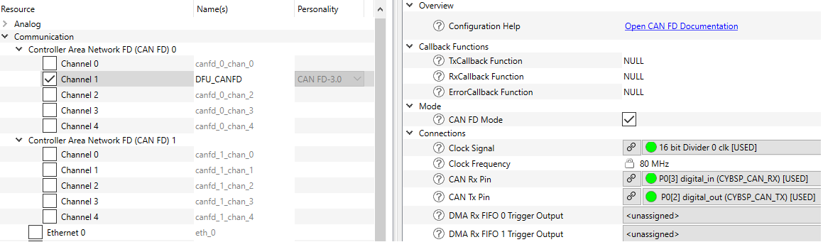
Use of the Device-Configurator™ tools for CAN-FD HW initialization
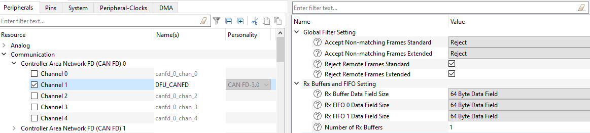
To set up the CAN FD personality in the ModusToolbox™ Device Configurator for the CAN FD DFU transport for PSOC Control C3, see the screenshots below. For other devices, verify the CAN Rx and CAN Tx pins connections.
General settings - set the personality alias and CAN FD mode:
| Parameter name | Value |
| Personality alias name | DFU_CANFD |
| CAN FD Mode | Enabled |
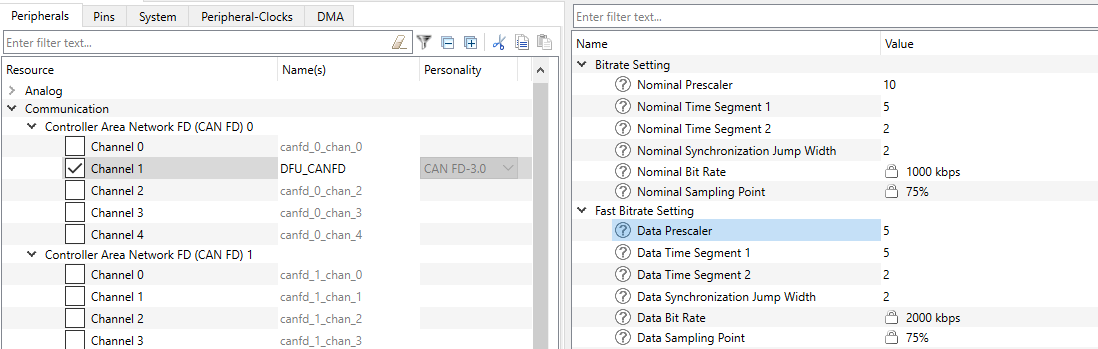
Bitrate settings - configure prescaler, time segments and syncronization jump width:
| Parameter name | Value |
| Nominal Prescaler | Set according to nominal bitrate setting in the DFU Host Tool |
| Nominal Time Segment 1 |
| Nominal Time Segment 1 |
| Nominal Syncronization Jump Width |
| Data Prescaler | Set according to data bitrate setting in the DFU Host Tool |
| Data Time Segment 1 |
| Data Time Segment 1 |
| Data Syncronization Jump Width |
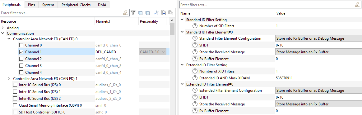
ID Filter settings - configure standard or extended frame ID filter:
| Parameter name | Value |
| Number of SID Filters | 1 if standard frame is used, 0 otherwise |
| Number of XID Filters | 1 if extended frame is used, 0 otherwise |
| Standard Filter Element Configuration | Store into Rx Buffer or as Debug Message |
| SFID1/EFID1 | As configured in the DFU Host Tool |
| Store the Received Message | Store Message into an Rx Buffer |
| Rx Bufer Element | 0 |
Global Filter & Rx Buffers settings - configure global filter and Rx buffer:
| Parameter name | Value |
| Accept Non-matcing Frames Standard | Reject |
| Accept Non-matcing Frames Extended | Reject |
| Reject Remote Frames Standard | Enabled |
| Reject Remote Frames Extended | Enabled |
| Rx Bufer Data Field Size | 64 Byte Data Field |
| Number of Rx Buffers | 1 |
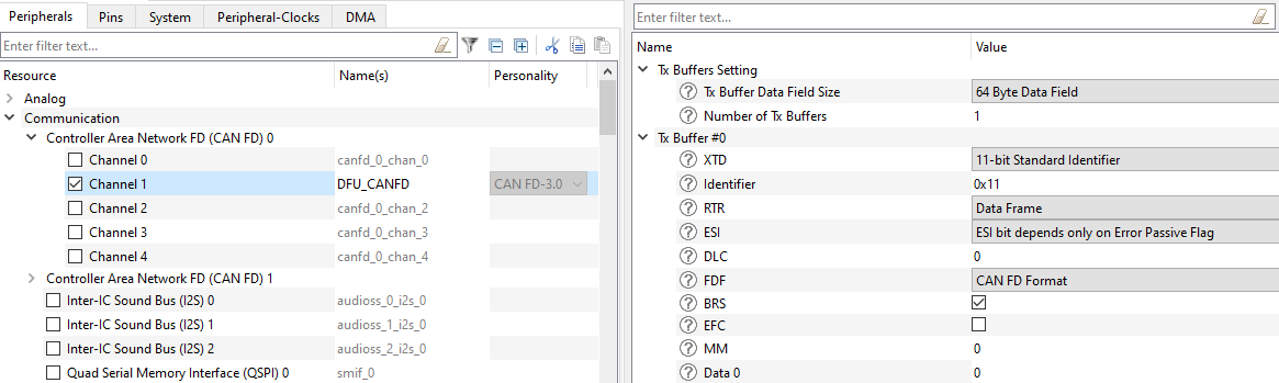
Tx Buffers & Tx Buffer #0 settings - configure Tx buffer:
| Parameter name | Value |
| Tx Bufer Data Field Size | 64 Byte Data Field |
| Number of Tx Buffers | 1 |
| XTD | As configured in the DFU Host Tool |
| Identifier |
| BRS |
| FDF | CAN FD Format |
- Note
- DLC and Data will be set by the middleware according to the specific transaction.
DFU logging
The DFU Middleware provides the possibility to the enable logging feature. The logging can be enabled by adding CY_DFU_LOG_LEVEL with selected log level to DEFINES variable in Makefile:
See the available log levels - DFU Log Levels.
By default, the logs are printed by the retarget-io middleware. So, initialize this middleware on the application level. If another output method is required, redirect the DFU logging by adding CY_DFU_CUSTOM_LOG to DEFINES variable in Makefile and provide custom implementation of the Cy_DFU_Log() function. Also, you can redefine the buffer size by CY_DFU_LOG_BUF.
- Note
- If you select CY_DFU_LOG_LEVEL_INFO or CY_DFU_LOG_LEVEL_DEBUG as log levels, too many log messages can be printed which leads to different fails (For example, a timeout from the DFU Host tool side). Especially, this is applicable when the DFU transport works at a speed faster than the logging and the size of packets is small. Recommended:
- Increase the data speed of the logging method and decrease the DFU transport speed
- Increase the packet size
- Use a smaller image size
- Add or increase a timeout for the command in the DFU Host tool.
DFU packet size increasing (I2C, SPI, UART)
The DFU middleware supports the packet size increasing. The default packet size is 32 bytes.The packet size can be increased up to 4048 bytes (see DFUH Tool for packet max size). To increase the packet size:
- Create a new .mtbdfu file with the desired packet size (see DFUH Tool User Guide for details)
- Packet size could be define for Send Data command in the .mtbdfu file in dataLength value
- The dataLength should not be greater than flashRowLength
- Ensure that CY_NVM_SIZEOF_ROW value is equal to flashRowLength in .mtbdfu file
- For I2C interface ensure that DFU_I2C_RX_BUFFER_SIZE is enough to handle the increased packet size It should be at least size of dataLength + 16 bytes to handle max size packet For max packet size like 4K timeout may need to be increased (CY_DFU_TRANSPORT_WRITE_TIMEOUT and cy_stc_dfu_params_t)
Change checksum types
DFU supports two types of checksums:
- transport packet checksum
- application image checksum.
For a packet, DFU supports 2 types of checksums: Basic summation and CRC-16CCITT. The basic summation checksum is computed by adding all the bytes (excluding the checksum) and then taking the 2's complement. CRC-16CCITT - the 16-bit CRC using the CCITT algorithm. The packet checksum type is selected with a macro CY_DFU_OPT_PACKET_CRC in dfu_user.h file: 0 - basic summation (default), 1 - for CRC-16.
Changelog
| Version | Changes | Reason for Change |
| 6.1.0 | Add support of PSOC™ Edge E84 MCUs devices | New device support |
| 6.0.0 | Migrate DFU middleware to the HAL Next flow | |
| 5.2.0 | Added USB HID transport based on the emUSB-Device middleware for the CAT1A device | Extending the current feature |
| Added CANFD transport based on the PDL driver for the CAT1C device | Extending the current feature |
| Minor updates in the templates | Improved the templates usability |
| Fixed address validation for CAT1C device | Bugfix |
| 5.1.0 | Added USB CDC transport based on the emUSB-Device middleware for the CAT1A device | Extending the current feature |
| Minor updates in the templates | Improved the templates usability |
| Corrected the name of the UART object used in the cyhal_uart_set_baud() function | Now, works correctly the custom baud rate configuring in the UART transport |
| 5.0.0 | Add support of the MCUBoot flow. | New functionality. |
| Add support of the transport switching at the run time. | New functionality. |
| CAT1 device flash read/write operation and I2C/SPI/UART transport templates updated to use mtb-hal-cat1 drivers instead of mtb-pdl-cat1. | Enhance code portability. |
| Removed Cy_DFU_Complete function as not used. | Code cleanup. |
| Removed CAT1A BLE transport templates. | BLESS stack is not supported in the MTB 3.0. |
| 4.20 | Added USB CDC transport configuration for the CAT2 PDL. | Add support for the USB interface for the PMG1 device family. |
| Updated timeout time for the CAT1A SPI transport. | Fixed the DFU Host Tool timeout error for the CAT1A SPI transport caused by the incorrect function call (transport_spi.c file, SPI_SpiCyBtldrCommRead() function). |
| Minor documentation update. | Documentation improvement. |
| 4.10 | Added PSoC 4 devices support. | Extended device support. |
| Added MISRA-C:2012 compliance. | MISRA standard compliance. |
| Updated SPI communication timeout granularity. | Fixed SPI communication issue. |
| 4.0 | Updated the linker scripts to use the single pre-compiled CM0p image. The upgradeable part of the image is the CM4 application. | Support ModusToolbox v2.0 build flow. |
| Added the ARM compiler version 6 support (version 5 is not supported). | |
| Added the USB interface (virtual COM port) transport template. | |
| Removed the Secure Application Formats support. | Secure Application Formats is not supported in ModusToolbox v2.0 build flow. |
| Fixed the return value for the SYNC command processing. | The SYCN command returned fail after successful execution. |
| Updated the major and minor version defines to follow the naming convention. | |
| 3.10 | Remove the function prototype from the MDK linker script include file. | Fix the linker error for the MDK compiler. |
| Add BLE transport templates. | Add BLE middleware support. |
| 3.0 | Bootloader SDK is renamed to the DFU (Device Firmware Update) SDK. All API prefixes and file names are renamed accordingly.
Added BWC macros to simplify migration. | Avoid the confusion with the device boot-up and OS load. |
| Flattened the organization of the driver source code into the single source directory and the single include directory. | Driver library directory-structure simplification. |
| 2.20 | Add check of application number in Set Application Metadata command processing routine. | Prevent incorrect usage of the Set Application Metadata command. |
| Minor documentation updates | Documentation improvement |
| 2.10 | Moved address and golden image checks from cy_dfu.c to Cy_DFU_WriteData() in dfu_user.c, so the checks can be customized based on application needs. | Allows receiving an update for the running app use case. Improvements made based on usability feedback. Documentation update and clarification. |
| 2.0 |
-
Use the shared RAM for application switching instead of the BACKUP register.
-
Add support of secure application verification.
-
Add support of I2C/SPI/BLE transport protocols.
-
Linker scripts updated for PSoC6 Rev *A devices.
-
Made CRC default application checksum.
| To increase functionality. |
| 1.0 | Initial version. | |
More Information
For more information, refer to the links in the README.md