 |
Cypress PSoC 6 Bluetooth Low Energy Middleware Library 3.60
|
|
Cypress PSoC 6 Bluetooth Low Energy Middleware Library 3.60
|
This section explains how to configure the Bluetooth Low Energy (BLE) middleware for operation in either:
The following figure shows the common flow for PSoC 6 BLE Middleware configuration:
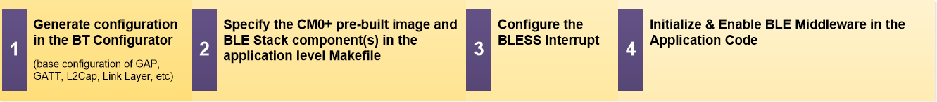
Refer to the following sections for BLE configuration details:
The generated files contain the BLE configuration structure, cy_ble_config (type of cy_stc_ble_config_t ), and a set of macros that can be used in the application. Refer to ModusToolbox BT Configurator Tool Guide.
The BLE stack components and the pre-compiled image for the CM0+ BLE Sub-system (BLESS) controller are parts of the PSoC 6 BLE Middleware that include different variants of pre-built BLE stack libraries.
The user may specify the BLE stack components and CM0+ pre-built image via the COMPONENTS variable in the application level Makefile. The following table describes all the BLE stack components, pre-built images, and the relationship between them in different BLE operating modes:
| Components (libraries / pre-built images) | Description | BLE Operation Modes | ||
| Complete BLE Protocol | BLE HCI (over Software API) | |||
| BLE Dual CPU Mode (Host part) | BLE Single CPU Mode | |||
| BLESS_HOST_IPC | BLE stack host (over IPC) pre-built libraries that run on the CM4 core in BLE Dual CPU mode. Must be complemented with the CM0+ BLESS controller pre-compiled image (CM0P_BLESS). There are soft FP and hard FP variants. | Y | ||
| BLESS_HOST | BLE stack host (over software transport interface) pre-built libraries that run on the CM4 core in BLE Single CPU mode. Must be complemented with the BLE Stack controller (over software transport interface) component (BLESS CONTROLLER). There are soft FP and hard FP variants. | Y | ||
| BLESS_CONTROLLER | BLE stack controller (over software transport interface) pre-built libraries that run on the CM4 core in BLE Single CPU or Host Controller Interface (HCI) modes. There are soft FP and hard FP variants. | Y | Y | |
| CM0P_BLESS | This image has the BLE controller implementation. It starts the CM4 core at CY_CORTEX_M4_APPL_ADDR=0x10020000. It then goes into a while loop where it processes BLE controller events and puts the CM0+ core into CPU deep sleep. | Y | ||
| CM0P_SLEEP | This image starts the CM4 core at CY_CORTEX_M4_APPL_ADDR=0x10002000 and puts the CM0+ core into CPU deep sleep. | (Y) | (Y) | |
| Other CM0+ images | Pre-compiled application images executed on the Cortex M0+ core of the PSoC 6 Dual-core MCU. The images are provided as C arrays ready to be compiled as part of the Cortex M4 application. The Cortex M0+ application code is placed in internal flash by the Cortex M4 linker script. | (Y) | (Y) | |
The following fragments of the application level Makefile show how to enable different BLE modes.
| Dual CPU mode | Single CPU mode | HCI mode |
| APPNAME=BLE_APP_DUAL_CORE COMPONENTS=BLESS_HOST_IPC CM0_BLESS | APPNAME=BLE_APP_SINGLE_CORE COMPONENTS=BLESS_HOST BLESS_CONTROLLER | APPNAME=BLE_HCI_APP COMPONENTS=BLESS_CONTROLLER |
The BLE stack libraries are compliant with the Arm Embedded Application Binary Interface (EABI). They are compiled with the Arm compiler version 5.03. The following table shows the mapping between the BLE stack libraries and the user-configured COMPONENT:
| COMPONENT Name | Library Name/Path in PSoC 6 BLE Middleware | Used for Toolchains (WCHAR) | SOFT/HARD Floating Point |
| BLESS_HOST_IPC | COMPONENT_BLESS_HOST_IPC/COMPONENT_SOFTFP/TOOLCHAIN_GCC_ARM/cy_ble_stack_host.a | GCC (WCHAR 32) | SOFTFP |
| COMPONENT_BLESS_HOST_IPC/COMPONENT_HARDFP/TOOLCHAIN_GCC_ARM/cy_ble_stack_host.a | HARDFP | ||
| COMPONENT_BLESS_HOST_IPC/COMPONENT_SOFTFP/TOOLCHAIN_IAR/cy_ble_stack_host.a | IAR (WCHAR 32) | SOFTFP | |
| COMPONENT_BLESS_HOST_IPC/COMPONENT_HARDFP/TOOLCHAIN_IAR/cy_ble_stack_host.a | HARDFP | ||
| COMPONENT_BLESS_HOST_IPC/COMPONENT_SOFTFP/TOOLCHAIN_ARM/cy_ble_stack_host.ar | Arm Compiler 6 (WCHAR 16) | SOFTFP | |
| COMPONENT_BLESS_HOST_IPC/COMPONENT_HARDFP/TOOLCHAIN_ARM/cy_ble_stack_host.ar | HARDFP | ||
| BLESS_HOST | COMPONENT_BLESS_HOST/COMPONENT_SOFTFP/TOOLCHAIN_GCC_ARM/cy_ble_stack_host.a | GCC (WCHAR 32) | SOFTFP |
| COMPONENT_BLESS_HOST/COMPONENT_HARDFP/TOOLCHAIN_GCC_ARM/ cy_ble_stack_host.a | HARDFP | ||
| COMPONENT_BLESS_HOST/COMPONENT_SOFTFP/TOOLCHAIN_IAR/ cy_ble_stack_host.a | IAR (WCHAR 32) | SOFTFP | |
| COMPONENT_BLESS_HOST/COMPONENT_HARDFP/TOOLCHAIN_IAR/cy_ble_stack_host.a | HARDFP | ||
| COMPONENT_BLESS_HOST/COMPONENT_SOFTFP/TOOLCHAIN_ARM/cy_ble_stack_host.ar | Arm Compiler 6 (WCHAR 16) | SOFTFP | |
| COMPONENT_BLESS_HOST/COMPONENT_HARDFP/TOOLCHAIN_ARM/cy_ble_stack_host.ar | HARDFP | ||
| BLESS_CONTROLLER | COMPONENT_BLESS_CONTROLLER/COMPONENT_SOFTFP/TOOLCHAIN_GCC_ARM/cy_ble_stack_controller.a | GCC (WCHAR 32) | SOFTFP |
| COMPONENT_BLESS_CONTROLLER/COMPONENT_SOFTFP/TOOLCHAIN_GCC_ARM/cy_ble_stack_manager.a | |||
| COMPONENT_BLESS_CONTROLLER/COMPONENT_HARDFP/TOOLCHAIN_GCC_ARM/cy_ble_stack_controller.a | HARDFP | ||
| COMPONENT_BLESS_CONTROLLER/COMPONENT_HARDFP/TOOLCHAIN_GCC_ARM/cy_ble_stack_manager.a | |||
| COMPONENT_BLESS_CONTROLLER/COMPONENT_SOFTFP/TOOLCHAIN_IAR/cy_ble_stack_controller.a | IAR (WCHAR 32) | SOFTFP | |
| COMPONENT_BLESS_CONTROLLER/COMPONENT_SOFTFP/TOOLCHAIN_IAR/cy_ble_stack_manager.a | |||
| COMPONENT_BLESS_CONTROLLER/COMPONENT_HARDFP/TOOLCHAIN_IAR/cy_ble_stack_controller.a | HARDFP | ||
| COMPONENT_BLESS_CONTROLLER/COMPONENT_HARDFP/TOOLCHAIN_IAR/cy_ble_stack_manager.a | |||
| COMPONENT_BLESS_CONTROLLER/COMPONENT_SOFTFP/TOOLCHAIN_ARM/cy_ble_stack_controller.ar | Arm Compiler 6 (WCHAR 16) | SOFTFP | |
| COMPONENT_BLESS_CONTROLLER/COMPONENT_SOFTFP/TOOLCHAIN_ARM/cy_ble_stack_manager.ar | |||
| COMPONENT_BLESS_CONTROLLER/COMPONENT_HARDFP/TOOLCHAIN_ARM/cy_ble_stack_controller.ar | HARDFP | ||
| COMPONENT_BLESS_CONTROLLER/COMPONENT_HARDFP/TOOLCHAIN_ARM/cy_ble_stack_manager.ar |
Pre-compiled BLESS controller image executed on the Cortex M0+ core of the PSoC 6 dual- core MCU. The image is provided as C arrays ready to be compiled as part of the Cortex M4 application. The Cortex M0+ application code is placed in internal flash by the Cortex M4 linker script. This image is used only in BLE Dual CPU mode. In this mode, the BLE functionality is split between CM0+ (controller) and CM4 (host). It uses IPC for communication between two CPU cores where both the controller and host run.
A BLESS controller pre-built image executes the following steps:
To use this image, update the ram, flash, and FLASH_CM0P_SIZE values in the linker script for CM4:
Example for the GCC compiler:
Example for the IAR compiler:
Example for the IAR compiler:
The interrupt is mandatory for PSoC 6 BLE Middleware operation. The BLESS hardware block provides interrupt sources. To configure interrupts, the Cy_BLE_BlessIsrHandler() function is called in the interrupt handler to process interrupt events generated by BLESS.
The BLESS interrupt is configured on the core where the BLE controller is running. The following table shows details of interrupt configuration depending on the BLE core modes.
| BLE Core mode | BLE Controller core | BLESS Interrupt configuration |
| Dual CPU mode | CM0+ | The BLESS interrupt is configured in the CM0+ BLESS controller pre-built image. |
| Single CPU mode | CM4 | cy_stc_sysint_t blessIsrCfg = { // The BLESS interrupt .intrSrc = bless_interrupt_IRQn, // The interrupt priority number .intrPriority = 1u }; Note. Priority level (intrPriority ) must have the highest value in system. |
The following code shows how to implement the ISR handler for the BLESS interrupt service. The Cy_BLE_BlessIsrHandler() function is called from BLESS ISR to process interrupt events generated by BLESS:
Finally, the BLESS interrupt is configured and interrupt handler routines are hooked up to NVIC. The pointer to the BLESS interrupt configuration structure (blessIsrCfg) is stored in the BLE configuration structure ( cy_ble_config):
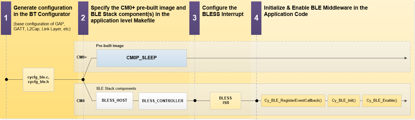
In this mode, the BLE functionality is entirely on the CM4 CPU core. It uses a software interface for communication between the controller and host. The following figure shows the configuration flow for the BLE middleware in Single CPU mode.
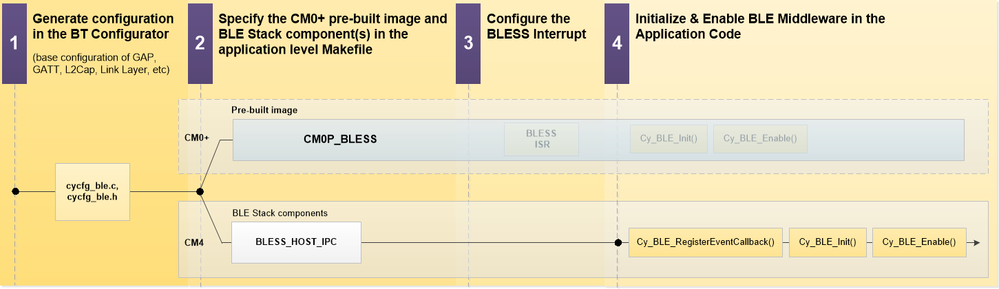
In this mode, the BLE functionality is split between the CM0+ (controller) and CM4 (host) CPU cores. The controller part is implemented in BLESS controller CM0+ pre-built image. It uses IPC for communication between the two CPU cores that run the controller and host.The following figure shows the configuration flow for the PSoC 6 BLE Middleware in Dual CPU mode:
The following code snippet shows the BLE initialization:

Send an HCI packet to the BLE stack controller
Use the Cy_BLE_SoftHciSendAppPkt() function to send an HCI packet to the BLE stack controller. The application allocates memory for the buffer to hold the HCI packet passed as an input parameter. This function copies the HCI packet into the controller's HCI buffer. Hence, the application may deallocate the memory buffer created to hold the HCI packet, once the API returns.
Receive an HCI event (or ACL packet) from BLE stack controller
Use the Cy_BLE_SoftHciSendAppPkt() function to send an HCI packet to the BLE stack controller. The application allocates memory for the buffer to hold the HCI packet passed as an input parameter. This function copies the HCI packet into the controller's HCI buffer. Hence, the application may deallocate the memory buffer created to hold the HCI packet, once the API returns.
This feature is used in the over-the-air (OTA) implementation. It allows sharing BLE component code between two component instances: one instance with profile-specific code and one with a stack. To configure OTA with code sharing, define CY_BLE_SHARING_MODE in the project. This parameter allows choosing between the following options:
| Option | Value | Description |
|---|---|---|
| Disabled | 0 | OTA with code sharing feature is disabled. |
| Stack and Profiles | 1 | This option is used to isolate the stack and the application Profiles. The following code snippet shows how to dynamically allocate memory for BLE stack: |
| Profile only | 2 | This option makes the middleware only have the profile-specific code. Stack is excluded. |