|
Hardware Abstraction Layer (HAL)
|
|
Hardware Abstraction Layer (HAL)
|
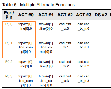
The PWM HAL driver allows generation of a normal and an inverted output. PSoC devices support complementary pin pairs to which the normal and inverted signals can be routed. To identify the complementary pin for a given pin, open the PSoC device datasheet and navigate to the 'Multiple Alternate Functions' table. Each column represents an alternate function of the pin in the corresponding row. Find your pin and make a note of the tcpwm[X].line[Y]:Z. The complementary pin is found by looking up the pin against tcpwm[X].line_compl[Y]:Z from the same column. For example, the image below shows a pair of complementary pins (P0.0 and P0.1) identified by the tcpwm[0].line[0]:0 and tcpwm[0].line_compl[0]:0 mapping. These complementary pins can be supplied to cyhal_pwm_init_adv using pin and compl_pin parameters in any order.
On PSoC 6 devices, not all PWMs hardware blocks are of the same resolution. The resolution of the PWM associated with a given pin is specified by the TCPWM<idx>_CNT_CNT_WIDTH macro (provided by cy_device_headers.h in mtb-pdl-cat1), where <idx> is the index associated with the tcpwm portion of the entry in the pin function table. For example, if the pin function is tcpwm[1].line[3]:Z, <idx> would be 1.
By default, the PWM HAL driver will configure the input clock frequency such that all PWM instances are able to provide the same maximum period regardless of the underlying resolution, but period and duty cycle can be specified with reduced granularity on lower-resolution PWM instances. If an application is more sensitive to PWM precision than maximum period, or if a longer maximum period is required (with correspondingly reduced precision), it is possible to override the default clock by passing a cyhal_clock_t instance to the cyhal_pwm_init function with a custom frequency specified. See the Clock HAL documentation for more details.