Overview
The purpose of PMBus middleware is to provide a solution for the implementation of the SMBus/PMBus target device.
General Description
The PMBus middleware provides the in-build handling of pages and phases and supports:
- Target Mode
- PEC (Packet Error Code)
- SMBus protocols: Quick Command, Send Byte, Receive Byte, Write Byte/Word, Read Byte/Word, Process Call, Block Write/Read, Block Write-Read Process Call, Write 32/64, and Read 32/64
- Zone Read and Zone Write protocols
- Group Command Protocol
- Multi-instances
Quick Start Guide
This section provides a step-by-step guide to quickly get started with the PMBus Middleware. Namely: how to set up the PMBus Middleware in your project, configure the necessary hardware, and implement the basic SMBus/PMBus target functionality
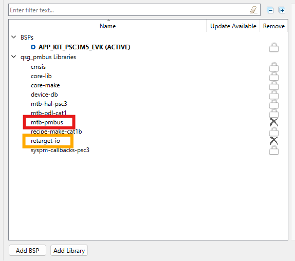
1. Add mtb-pmbus middleware to your project
- If you work in the ModusToolbox IDE, use the ModusToolbox Library Manager to add the mtb-pmbus middleware to your project. Otherwise, ensure that mtb-pmbus middleware is included into your project.
- Note
- Middleware uses printf() for logging purposes. To use printf() for the terminal output, add retarget-io middleware from the Library Manager or in any other way.
2. Configure SCB blocks and GPIO pins
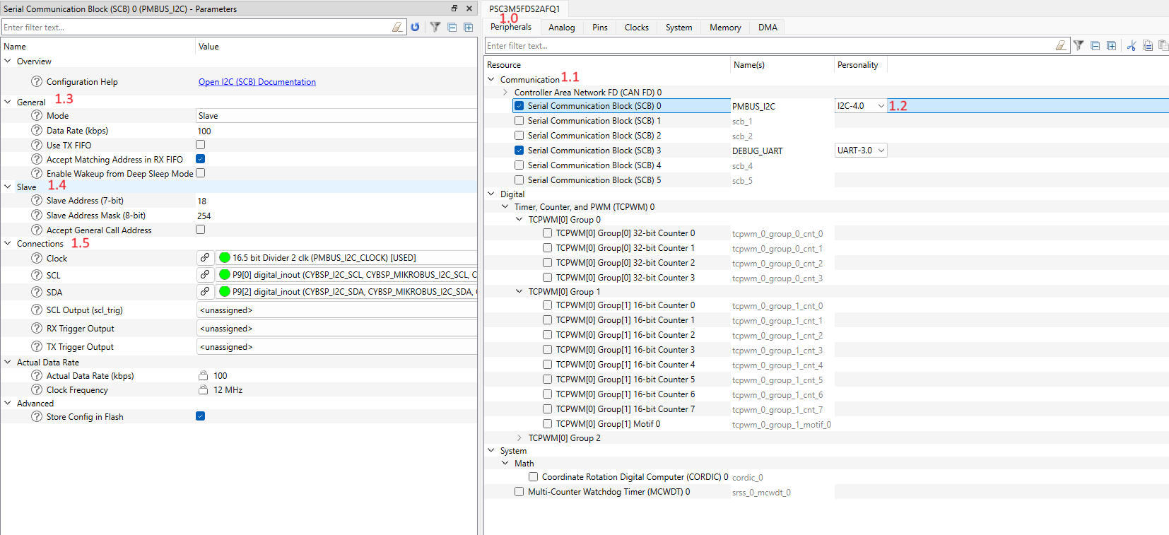
- Open the Device Configurator and switch to the Peripherals tab (#1.0).
- Enable the SCB block under Communication (#1.1) and select the I2C Personality (#1.2). Select the desired name for the SCB (e.g., PMBUS_I2C).
- In the "General" section (#1.3), choose Slave mode and set the I2C Data Rate to the desired value (e.g., 100 kHz). Disable the "Use TX FIFO" option and enable the "Accept Matching Address" in RX FIFO option.
- In the "Slave" section (#1.4), set the Slave Address to the desired SMBus/PMBus device address (e.g., 0x18).
- In the "Connect" section (#1.5), select the desired Clock for the SCB block. Also, select the desired pins for SDA and SCL lines, the Device Configurator will automatically configure them to Open Drain mode.
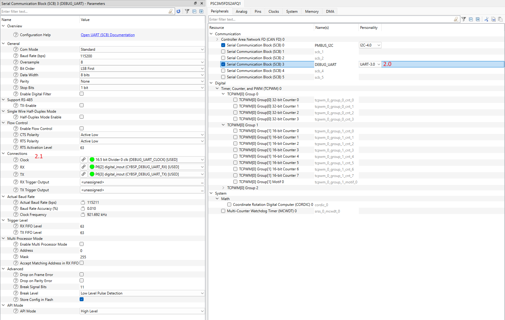
- Enable another SCB block under Communication and select UART Personality (#2.0). Select the desired name for the SCB. This block will be used for the debug output.
- Select the desired pins and clock for the SCB (#2.1). The other UART options can be set by default, see the screenshot.
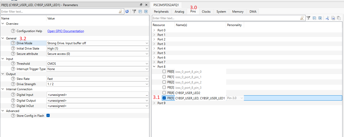
- Switch to the Pins tab (#3.0) and enable any User LED GPIO pin (#3.1). In the "General" section (#3.2) select the Strong Drive, input buffer off Drive mode.
- Select File->Save to generate initialization code.
3. Add SMBus/PMBus code to your project
This section describes the implementation of either an SMBus or PMBus target device. The implementation is similar for both protocols, with some differences in the command table and configuration. Both implementations support the Quick Command and Read Byte protocols, while the PMBus implementation additionally supports the PAGE command and Write/Read Word protocols with pages.
- Fill the mtb_pmbus_conf.h file with the desired compile-time configuration macros. This file will appear in the project import folder after adding the mtb-pmbus middleware.
#ifndef MTB_PMBUS_CONF_H
#define MTB_PMBUS_CONF_H
#include "mtb_pmbus_log_level.h"
#define MTB_PMBUS_LOG_LEVEL (MTB_PMBUS_LOG_LEVEL_DEBUG)
#define MTB_PMBUS_ENABLE_TIMEOUT (0U)
#endif
- Include the necessary headers files in main.c file:
#include "mtb_pmbus.h"
#include "cybsp.h"
#include "cy_retarget_io.h"
- Create variables for:
- Debug UART HAL object and context:
static cy_stc_scb_uart_context_t DEBUG_UART_context;
static mtb_hal_uart_t DEBUG_UART_hal_obj;
- I2C context:
static cy_stc_scb_i2c_context_t i2c_pdl_context;
- SMBus/PMBus instance:
Instance structure.
Definition: mtb_pmbus.h:1459
- Implement General event callback function:
static volatile uint8_t user_led_toggled_cnt = 0U;
{
{
printf("Gen: MTB_PMBUS_QUICK_CMD_WR_EVENT\n\r");
Cy_GPIO_Inv(CYBSP_USER_LED_PORT, CYBSP_USER_LED_PIN);
user_led_toggled_cnt++;
printf("User LED toggled\n\r");
}
}
mtb_pmbus_events_t
General events for PMBus Middleware.
Definition: mtb_pmbus.h:1125
@ MTB_PMBUS_QUICK_CMD_WR_EVENT
Quick command event with Write bit.
Definition: mtb_pmbus.h:1130
- Create buffers for SMBus/PMBus test commands:
- For PMBus project:
#define PMBUS_TEST_CMD_1_SIZE (1U)
#define PMBUS_TEST_CMD_2_SIZE (2U)
#define PMBUS_TEST_CMD_2_PAGES (2U)
static uint8_t pmbus_cmd1_buffer[PMBUS_TEST_CMD_1_SIZE] = {0U};
static uint8_t pmbus_cmd2_buffer[PMBUS_TEST_CMD_2_PAGES][PMBUS_TEST_CMD_2_SIZE] = {0U};
- For SMBus project:
#define PMBUS_TEST_CMD_1_SIZE (1U)
static uint8_t pmbus_cmd1_buffer[PMBUS_TEST_CMD_1_SIZE] = {0U};
- Implement the SMBus/PMBus command callback functions:
- For PMBus project:
{
(void) page;
(void) phase;
(void) byte;
{
printf("\n\rCMD1 match\n\r");
}
{
printf("\n\rCMD1 read request\n\r");
pmbus_cmd1_buffer[0] = user_led_toggled_cnt;
printf("Data buffer for read: 0x%02X\n\r", pmbus_cmd1_buffer[0]);
}
return true;
}
mtb_pmbus_cmd_events_t
Command specific events.
Definition: mtb_pmbus.h:1155
@ MTB_PMBUS_CMD_MATCH
Command match event.
Definition: mtb_pmbus.h:1160
@ MTB_PMBUS_CMD_READ_REQ
Read data is requested.
Definition: mtb_pmbus.h:1178
{
(void) byte;
(void) phase;
{
printf("\n\rCMD2 match\n\r");
printf("Data buffer for page %ld: 0x%02X 0x%02X\n\r", page, pmbus_cmd2_buffer[page][0], pmbus_cmd2_buffer[page][1]);
}
{
printf("\n\rCMD2 write done\n\r");
printf("Data buffer after write for page %ld: 0x%02X 0x%02X\n\r", page, pmbus_cmd2_buffer[page][0], pmbus_cmd2_buffer[page][1]);
}
return true;
}
@ MTB_PMBUS_CMD_WRITE_DONE
Write is completed.
Definition: mtb_pmbus.h:1173
- For SMBus project:
{
(void) page;
(void) phase;
(void) byte;
{
printf("\n\rCMD1 match\n\r");
}
{
printf("\n\rCMD1 read request\n\r");
pmbus_cmd1_buffer[0] = user_led_toggled_cnt;
printf("Data buffer for read: 0x%02X\n\r", pmbus_cmd1_buffer[0]);
}
return true;
}
- Implement the SMBus/PMBus command table:
- For PMBus project:
#define PMBUS_TEST_CMD_1_CODE (0x10U)
#define PMBUS_TEST_CMD_2_CODE (0x11U)
{
{
.data_buf = pmbus_cmd1_buffer,
.callback = pmbus_cmd1_callback,
.data_size = PMBUS_TEST_CMD_1_SIZE,
},
{
.cmd_code = PMBUS_TEST_CMD_2_CODE,
.data_buf = pmbus_cmd2_buffer,
.callback = pmbus_cmd2_callback,
.data_size = PMBUS_TEST_CMD_2_SIZE,
}
};
uint8_t cmd_code
Command code.
Definition: mtb_pmbus.h:1321
Command configuration structure.
Definition: mtb_pmbus.h:1319
#define MTB_PMBUS_CMD_CAP_FORMAT_8_BIT
The command uses 8 bit unsigned.
Definition: mtb_pmbus.h:972
#define MTB_PMBUS_CMD_CAP_PAGE
The command is paged.
Definition: mtb_pmbus.h:953
#define MTB_PMBUS_CMD_CAP_DIR_WR
The command supports write direction.
Definition: mtb_pmbus.h:944
#define MTB_PMBUS_CMD_CAP_DIR_RD
The command supports read direction.
Definition: mtb_pmbus.h:946
- For SMBus project:
#define PMBUS_TEST_CMD_1_CODE (0x10U)
{
{
.data_buf = pmbus_cmd1_buffer,
.callback = pmbus_cmd1_callback,
.data_size = PMBUS_TEST_CMD_1_SIZE,
}
};
- Implement I2C interrupt handler function:
void i2c_isr(void)
{
}
void mtb_pmbus_i2c_isr(mtb_pmbus_stc_t *inst)
PMBus Target interrupt service routine.
Definition: mtb_pmbus_hal.c:70
- Implement callback functions for:
- Enabling and disabling the I2C:
{
{
Cy_SCB_I2C_Enable(PMBUS_I2C_HW);
}
{
Cy_SCB_I2C_Disable(PMBUS_I2C_HW, &i2c_pdl_context);
}
}
mtb_pmbus_hw_resources_ctrl_action_t
I2C HW actions.
Definition: mtb_pmbus.h:1245
@ MTB_PMBUS_HW_RESOURCES_ENABLE
Enable the I2C HW.
Definition: mtb_pmbus.h:1247
@ MTB_PMBUS_HW_RESOURCES_DISABLE
Disable the I2C HW.
Definition: mtb_pmbus.h:1249
- Enabling and disabling I2C interrupts:
void hw_isr_enable(void)
{
NVIC_EnableIRQ((IRQn_Type) PMBUS_I2C_IRQ);
}
void hw_isr_disable(void)
{
NVIC_DisableIRQ((IRQn_Type) PMBUS_I2C_IRQ);
}
- Implement the SMBus/PMBus hardware configuration structure:
{
.pdl_i2c_context = &i2c_pdl_context,
};
{
.hw_resource_ctrl_callback = hw_resource_enable_callback,
.enable_hw_irq_callback = hw_isr_enable,
.disable_hw_irq_callback = hw_isr_disable
};
mtb_pmbus_stc_config_hal_t * hal_config
The pointer to HAL configuration structure, see mtb_pmbus_stc_config_hal_t.
Definition: mtb_pmbus.h:1336
Hardware configuration structure.
Definition: mtb_pmbus.h:1334
CySCB_Type * hw_ptr
The pointer to SCB.
Definition: mtb_pmbus_hal.h:86
HAL Configuration structure.
Definition: mtb_pmbus_hal.h:84
- Implement the SMBus/PMBus configuration structure:
- For PMBus project:
#define PMBUS_DEVICE_ADDRESS (0x18U)
#define PMBUS_CMD_TABLE_SIZE (2U)
#define PMBUS_TOTAL_NUM_PAGES (2U)
{
.address = PMBUS_DEVICE_ADDRESS,
.enable_pec = false,
.enable_smbalert = false,
.enable_pmbus = true,
.num_pages = PMBUS_TOTAL_NUM_PAGES,
.num_phases = 0U,
.enable_zone = false,
.cmd_table = cmd_table,
.cmd_num = PMBUS_CMD_TABLE_SIZE,
.enable_gen_call_addr = false,
.gen_callback = pmbus_gen_callback,
.errors_callback = NULL,
.enable_ieee_format = false,
};
mtb_pmbus_stc_config_hw_t * hw_config
Pointer to hardware configuration structure.
Definition: mtb_pmbus.h:1349
Configuration structure.
Definition: mtb_pmbus.h:1347
@ MTB_PMBUS_REVISION_1_4
PMBus revision 1.4.
Definition: mtb_pmbus.h:1259
@ MTB_PMBUS_SPEED_100
The maximum supported bus speed is 100 kHz.
Definition: mtb_pmbus.h:1270
#define MTB_PMBUS_IMPL_CMD_PAGE_EN
Enable the PAGE (0x00) command.
Definition: mtb_pmbus.h:1064
- For SMBus project:
#define PMBUS_DEVICE_ADDRESS (0x18U)
#define PMBUS_CMD_TABLE_SIZE (1U)
{
.address = PMBUS_DEVICE_ADDRESS,
.enable_pec = false,
.enable_smbalert = false,
.enable_pmbus = false,
.num_pages = 0U,
.num_phases = 0U,
.enable_zone = false,
.impl_cmd_mask = 0U,
.cmd_table = cmd_table,
.cmd_num = PMBUS_CMD_TABLE_SIZE,
.enable_gen_call_addr = false,
.gen_callback = pmbus_gen_callback,
.errors_callback = NULL,
.enable_ieee_format = false,
};
- (From this step add code to the main() function) Create variables for result statuses:
cy_rslt_t result;
cy_en_scb_uart_status_t init_status;
- Initialize the device and board peripherals:
result = cybsp_init();
if (result != CY_RSLT_SUCCESS)
{
CY_ASSERT(0);
}
- Initialize the UART for debug output:
init_status = Cy_SCB_UART_Init(DEBUG_UART_HW, &DEBUG_UART_config, &DEBUG_UART_context);
if (init_status!=CY_SCB_UART_SUCCESS)
{
CY_ASSERT(0);
}
Cy_SCB_UART_Enable(DEBUG_UART_HW);
result = mtb_hal_uart_setup(&DEBUG_UART_hal_obj, &DEBUG_UART_hal_config,
&DEBUG_UART_context, NULL);
if (result != CY_RSLT_SUCCESS)
{
CY_ASSERT(0);
}
result = cy_retarget_io_init(&DEBUG_UART_hal_obj);
if (result != CY_RSLT_SUCCESS)
{
CY_ASSERT(0);
}
printf("\x1b[2J\x1b[;H");
printf("************************************************************\r\n");
printf("PMBus Quick Start Guide CE\r\n");
printf("************************************************************\r\n\n");
- Enable irq:
- Initialize the I2C hardware:
Cy_SCB_I2C_Init(PMBUS_I2C_HW, &PMBUS_I2C_config, &i2c_pdl_context);
cy_stc_sysint_t i2c_isr_cfg =
{
.intrSrc = PMBUS_I2C_IRQ,
.intrPriority = 3U
};
Cy_SysInt_Init(&i2c_isr_cfg, i2c_isr);
MTB_PMBUS_LOG_INF("I2C transport is initialized");
- Initialize the SMBus/PMBus middleware instance:
{
MTB_PMBUS_LOG_DBG("PMBus initialization failed!");
}
else
{
{
}
}
mtb_pmbus_status_t
Used to return the statuses of most PMBus APIs.
Definition: mtb_pmbus.h:1088
@ MTB_PMBUS_STATUS_SUCCESS
Correct status.
Definition: mtb_pmbus.h:1090
mtb_pmbus_status_t mtb_pmbus_enable(mtb_pmbus_stc_t *inst)
Enable PMBus Middleware.
Definition: mtb_pmbus.c:170
mtb_pmbus_status_t mtb_pmbus_init(mtb_pmbus_stc_t *inst, mtb_pmbus_stc_config_t const *config)
Initialize the PMBus Middleware.
Definition: mtb_pmbus.c:57
4. Check the SMBus/PMBus workability
- Build and program your project.
- Open a terminal application (e.g., PuTTY, Tera Term) and connect to the device's COM port.
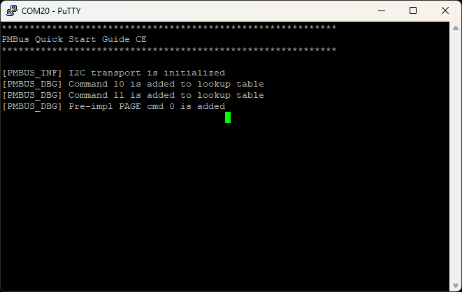
- Check if I2C transport is initialized correctly and all commands are registered.
- Connect the I2C Controller to the device.
Quick Command and Read Byte protocols test(SMBus/PMBus mode):
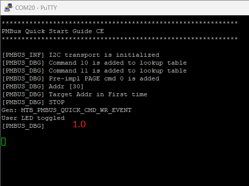
- Send Quick Command with the write direction to the device address(The User LED will toggle(#1.0))).
- Repeat the previous step with Quick Command several more times.
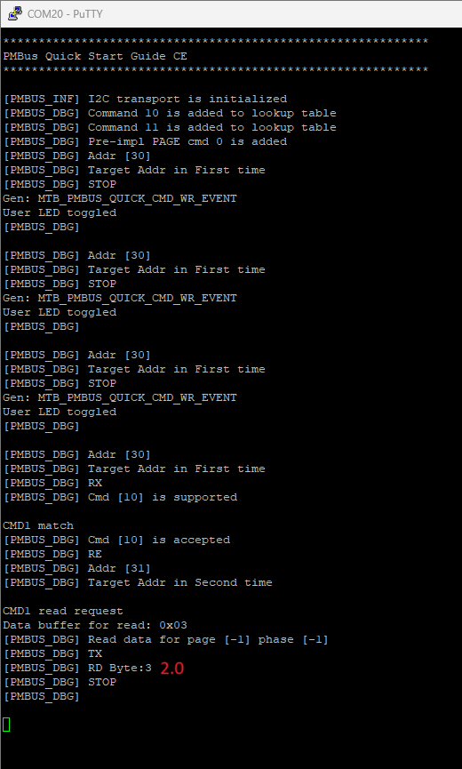
- Send Read Byte protocol with CMD1 command code (0x10) to the device address (the controller will read User LED toggle counter(#2.0)).
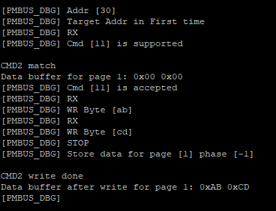
Implemented PAGE command and Write/Read Word protocols with page support test(PMBus mode only):
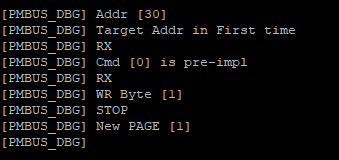
- Send Write Word to the device address with PAGE command code(0x00) and page number (0x01) (Target will switch to page 1).
- Send Write Word to the device address with CMD2 command code (0x11) and data bytes (0xAB 0xCD) (Target will write command data buffer on page 1).
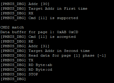
- Send Read Word to the device address with CMD2 command code (Controller will read data from command data buffer on page 1).
Design Considerations
Initialization sequence
First, initialize the hardware resources for the PMBus Middleware without enabling it. The middleware determines when to enable the hardware resources. For this purpose, provide the following callbacks:
After the hardware resources are initialized, call the mtb_pmbus_init function. After initialization, you can update the default configuration of the middleware:
- Update the contents of the command buffer
- Disable and/or protect specific commands
- Update the default Zone Read/Write settings (required only in specific cases, typically the controller assigns the Zone Read/Write values)
- Select the active page/phase (required only in specific cases, typically the controller selects the active page/phase)
- Note
- The mtb_pmbus_init function must be called before any other APIs to initialize the instance structure. A call to the other APIs before the init function can lead to unexpected behavior including a hard fault error.
After completing the initial configuration, call the mtb_pmbus_enable function. After calling mtb_pmbus_enable, the middleware starts responding on the bus.
The contents of the mtb_pmbus_stc_config_hw_t, mtb_pmbus_stc_config_t, and mtb_pmbus_stc_config_cmd_t structures are not modified by the middleware, so they can be allocated in flash or RAM as needed. However, these structures must remain available for as long as the PMBus instance is active, and their contents are expected to remain unchanged after calling mtb_pmbus_init.
The contents of mtb_pmbus_stc_t are internal and not subject to modification by the application. The mtb_pmbus_stc_t structure is continuously updated by the middleware and therefore must be located in RAM.
mtb_pmbus_enable can only be called after mtb_pmbus_init.
The middleware does not provide a deinit function. To update the configuration, use the following sequence:
- mtb_pmbus_disable
- mtb_pmbus_init
- mtb_pmbus_enable
The PMBus Middleware does not deinitialize the hardware resources. If the PMBus instance is disabled and no longer required, releasing the hardware resources is the responsibility of the application.
Communication Protocols
The PMBus Middleware supports multiple protocols defined in SMBus and PMBus specifications. This section provides implementation specific details in addition to the specifications.
Quick Command vs Received Byte Protocols: The Quick Command with the Read direction bit and the Received Byte protocol are identical during the Address stage of the transfer. As a result, the target device cannot distinguish between them in time, which may lead to an error condition on the bus.
- Note
- After the last SCL clock for the ACK/NACK bit of the address part, the target starts to set the first bit of the Received Byte protocol. At the same time, if a Quick Command is initiated, the controller sets the SDA line to a low level to generate the STOP condition. Then, after setting the SCL line to a high level, the following cases can occur on the bus:
- If the first bit of the Received Byte is 1, the controller wins arbitration and completes the transfer with a STOP condition. From the target's point of view, such a sequence of events on the bus is considered as arbitration lost.
- If the first bit of the Received Byte is 0, the target continues holding the SDA line, which prevents the STOP event generation, and most likely a timeout error will be generated after 25 ms.
As a result, you can use Quick Command and Received Byte as follows:
- If only one protocol, either Quick Command or Received Byte, is used, no collision/errors occur on the bus.
- Note
- If the Quick Command is initiated by the controller and the Received Byte is disabled in the middleware, the middleware sends the 0xFF byte after the address part of the transfer and ignores the arbitration lost event. Sending 0xFF allows the controller to win arbitration.
- No issue if only Quick Command with the Write direction and Received Byte are used.
- If both Quick Command with Read direction and Received Byte are used, the first bit of the Received Byte must always be set to 1 to allow the controller to win arbitration in the case of Quick Command.
- Note
- For this case, the arbitration lost event is also ignored and the middleware does not report it to the application level.
Zone Read and Write Protocols: The Middleware handles the Zone Read and Zone Write protocols, assigning new zones to the pages and tracking the new active zones on the bus automatically. Also, the Middleware cares about Command Control code and determines the type of actions (Status or Command), the byte ordering, bit swapping and respond mode. So, the commands handling is very similar to standard protocols. Also, to read/write command data, the Zone Read protocol can be used to request the status. The Middleware reports the requested status bits through in callback to application, see mtb_pmbus_zone_events_t.
To enable Zone protocols execute the next steps:
Zone Write and Zone Read command handling From User point of view, the commands handling during the Zone protocols is almost the same as for standard protocols. The only difference is that during Zone Read protocol, the lost arbitration event may occur when the Middleware loses arbitration to another target. To ensure that Controller completes the read of the command, always check if MTB_PMBUS_CMD_DONE event has occurred.
By default, after initialization of PMBus instance, the 0xFE zone is assigned for all pages. It is expected that the proper zone values are assigned by Controller or manually use the mtb_pmbus_set_default_zones function.
Zone protocols rely on the pages, but if pages are disabled for PMBus instance, the Zone Write and Zone Read are assigned globally for the whole instance.
Timeout Handling
The SMBus specification defines a few timeouts:
- Detect clock low timeout (tTIMEOUT)
- Cumulative clock low extend time (target device) (tLOW:TEXT)
- Cumulative clock low extend time (controller device) (tLOW:CEXT)
This middleware only detects the tTIMEOUT condition. The Timeout handling is a compile-time option.
- Note
- Under standard configuration, the middleware does not violate tLOW:TEXT. However, enabling logging can significantly impact the response time to received addresses and bytes, making it easy to exceed the cumulative clock low extend time.
Callback Handling
The PMBus Middleware provides multiple callbacks. Almost all callbacks are called inside the ISR handler, so these callback functions must be optimized for usage in ISR.
Command callback
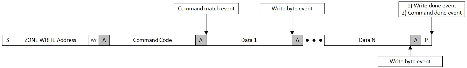
Each command may have its own callback. This callback is registered in the command config structure, see mtb_pmbus_stc_config_cmd_t::callback. The list of events is available in mtb_pmbus_cmd_events_t. The callback is called only with one event at a specific time moment.
Besides the event, the PMBus Middleware also informs about the active page/phase and the received byte. The received byte is actual only for the MTB_PMBUS_CMD_WRITE_BYTE event. If the command is not paged and/or phased, the page/phase parameters must be ignored.
The callback can return the bool value, this value is ignored for all events except MTB_PMBUS_CMD_WRITE_BYTE. For the MTB_PMBUS_CMD_WRITE_BYTE event, the return value will indicate which response (true - ACK, false - NACK) to send after receiving the data byte. The MTB_PMBUS_CMD_WRITE_BYTE event is triggered only for data bytes, for example, byte-count byte for Block Write/Read is completely handled inside the middleware.
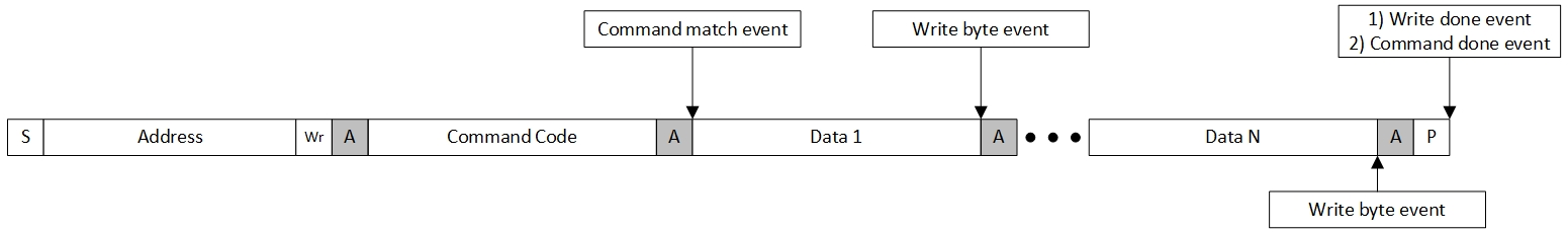
Events visualization for write transfer:
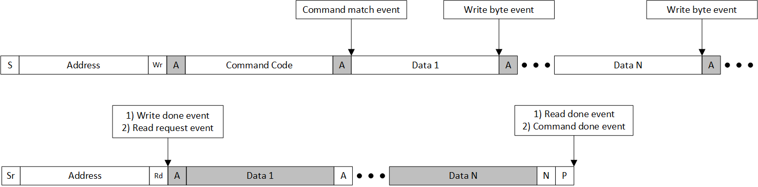
Events visualization for read transfer:
Events visualization for process call transfer:
Events visualization for Zone Write transfer:
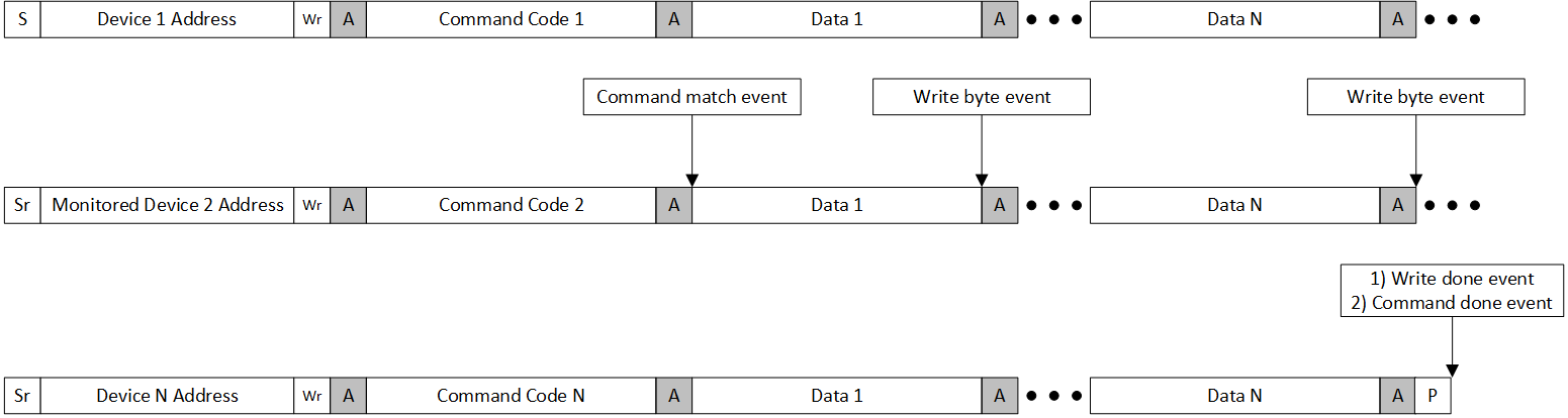
Events visualization for Group Command transfer. Callback triggering is analyzed for Device 2:
General callback
The PMBus Middleware provides two common callbacks: one for general events (see mtb_pmbus_handle_cmd_events_t) and one for Zone features (see mtb_pmbus_handle_zone_events_t). The general events callback is required only if any of these events are used by the application. The middleware always responds to Quick Command with both RD and WR directions as required by the SMBus/PMBus specification, always sending an ACK after receiving the target address. Additionally, the middleware sends a byte in the Received Byte callback with the default value is 0xFF.
- Note
- When PMBus mode is enabled, a target address with the RD direction is considered a data content fault. The middleware still sends an ACK after receiving the address but generates the corresponding error in the mtb_pmbus_handle_error_events_t callback.
The mtb_pmbus_handle_error_events_t callback is also used to report communication errors. This callback is typically invoked when a STOP condition occurs on the bus or when an extraordinary sequence of events happens, such as a bus error or timeout. It is important for the application to use this callback to provide the correct response to fault events. The application can ignore handling certain error events if they are not relevant to the features in use. For example, there is no need to handle PMBus-specific events when only SMBus mode is enabled.
Command Organization
The PMBus Middleware supports configuration of multiple pages and phases for commands.
Page/Phase configuration for commands. The command supports two types of configuration:
The same command can be paged and phased or only paged or only phased or neither.
- If a command is paged/phased, implement a two-dimensional array for the data buffer:
cmd_data[NUM_PAGES][DATA_SIZE]
cmd_data[NUM_PHASES][DATA_SIZE]
- If a command is paged and phased at the same time, a three-dimensional array is required for the data buffer:
cmd_data[NUM_PAGES][NUM_PHASES][DATA_SIZE]
- Note
- For the block write/read protocols, increment the DATA_SIZE by one byte. This additional byte is necessary to store the byte number within the package.
Command Capabilities
The commands have multiple capabilities, which define the command behavior. Refer to Command capabilities macro for more information.
Implemented Commands
The PMBus Middleware has implemented several commands from PMBus specification. Usage of implemented commands is optional and command's own implementation can be provided through the general command table.
Perform the next steps to use implemented commands:
- Enable implemented command by a corresponding compile time macro in the mtb_pmbus_conf.h file by setting the macro to 1 (this setting is applicable for all instances).
- Add the corresponding run time macro to mtb_pmbus_stc_config_t::impl_cmd_mask (this setting is applicable only for specific instances)
- Ensure that a command with the same code is not defined in the main command table: mtb_pmbus_stc_config_t::cmd_table
List of implemented commands:
Data Format conversion functions
The PMBus Middleware provides a set of functions to convert data between PMBus data formats and Float32 format. The conversion functions are:
- Note
- LINEAR11 and LINEAR16 are less precise than Float32, so conversion from Float32 to PMBus LINEAR11/16 may lead to loss of precision.
-
Mantissa of PMBus LINEAR11 and LINEAR16 are not normalized. So different combinations of mantissa and exponent may lead to the same value when converted to Float32:
0x0004(LIN11 HEX) -> 0 exponent, 4 mantissa -> 4.0f;
0x1001(LIN11 HEX) -> 2 exponent, 1 mantissa -> 4.0f;
0xCA00(LIN11 HEX) -> -7 exponent, 512 mantissa -> 4.0f;
Optional Signals
The SMBus and PMBus specifications specify a set of optional signals. The middleware supports some of them.
Logging
The PMBus Middleware provides the possibility to enable the logging feature. The logging can be enabled by defining MTB_PMBUS_LOG_LEVEL with the selected log level in mtb_pmbus_conf.h file. See the available log levels - Logging level.
By default, the logs are printed by the retarget-io middleware. So, initialize this middleware at the application level. If another output method is required, redirect the PMBus logging by defining MTB_PMBUS_CUSTOM_LOG in the mtb_pmbus_conf.h file and provide custom implementation of the mtb_pmbus_log function. Also, you can redefine the buffer size by MTB_PMBUS_LOG_BUF.
- Note
- If you select MTB_PMBUS_LOG_LEVEL_INFO or MTB_PMBUS_LOG_LEVEL_DEBUG as the log levels, too many log messages can be printed, which leads to a timeout error on the bus. Recommended:
- Increase the data speed of the logging method
- Redirect the logging data to the buffer and print messages after transfers
Low Power Support
The Middleware can operate only in power modes supported by the corresponding I2C/Timer hardware. Typically, only Active and Sleep modes are supported.
Compile Time Options
The PMBus Middleware provides the opportunity to disable unused features to reduce the memory footprint and improve the speed of code execution. The Compile Time Options are applicable for all instances, so if Instance 0 uses PEC and Instance 1 does not use it, the MTB_PMBUS_SUPPORT_PEC compile time option must be enabled.
Also, if you disable some of the compile time options, not all APIs will be available. For example: mtb_pmbus_stc_config_t::enable_pec is available only if MTB_PMBUS_SUPPORT_PEC is set to 1U.
Use the mtb_pmbus_conf.h file to reflect PMBus Middleware configuration in your application. This file will be automatically copied into your project once the middleware is added by the Library Manager.
The list of Compile Time Option and their default values: Compile Time Options
Hardware-dependent layer
Limitations and exeptions of the Zone feature
According to the PMBus specification, during a ZONE_READ transaction, the controller generates an Acknowledge (ACK) bit for the last byte read before issuing a repeated start condition. This behavior contradicts the I2C specification, which states that a read transaction must end with a Not Acknowledge (NACK) bit to indicate that the last byte has been read. The PMBus middleware is built on top of the I2C communication block, so it cannot reliably detect a restart or stop event during a read transaction if the last byte read by the controller was acknowledged with an ACK bit.
Note the ZONE_READ with PEC case: a sequence that also cannot be correctly recognized by the middleware due to hardware limitations, occurs before the stop event when receiving data from the last device in the zone: /Read last data byte/NACK/PEC/NACK/STOP.
Timeout Detection HW Implementations
Employs an external timer triggered by a signal from the communication line, such as the SCL. This solution relies on the internal connection between the communication line and a timer to generate a trigger signal, thereby facilitating the timeout handling.
Timeout Detection Configuration
To enable Timeout Detection, use macro MTB_PMBUS_ENABLE_TIMEOUT.
To initialize the TCPWM timeout handling, follow these steps:
- Open the Device Configurator: Navigate to the Peripherals tab and enable the TCPWM as the Timer-Counter.
- Configure TCPWM; Assign the peripheral clock to the Timer-Counter and set Run mode to One shot in the General section.
- Set Period: Set the Period in the General section calculated as TIMER_FREQUENCY_CLOCK * 0.025.
- Configure Compare: Select the Compare option as Compare and set the Compare value to the same value as the Period.
- Configure Interrupt Source: Go to the Interrupt Source section and enable the Compare and Capture checkbox.
- Configure Inputs: Move to the Inputs section, select the Stop Input as Rising Edge, and assign the scl_filtered signal of SCB to the Stop Signal.
- Configure Reload Input: Select the Reload Input as Falling Edge and assign the scl_filtered signal of SCB to the Reload Signal.
- Add Initialization Code: Add the following code to the HW initialization:
- Create the Timer IRQ handler:
void timer_isr(void)
{
}
void mtb_pmbus_timer_isr(mtb_pmbus_stc_t *inst)
PMBus Timer interrupt service routine.
Definition: mtb_pmbus_hal.c:50
- Initialize the Timer:
cy_en_tcpwm_status_t pdl_tcpwm_status = Cy_TCPWM_Counter_Init(PMBUS_TIMEOUT_HW, PMBUS_TIMEOUT_NUM, &PMBUS_TIMEOUT_config);
if (CY_TCPWM_SUCCESS != pdl_tcpwm_status)
{
MTB_PMBUS_LOG_ERR("Error during TCPWM PDL initialization. Status: %X", pdl_tcpwm_status);
}
else
{
cy_stc_sysint_t timer_isr_cfg =
{
.intrSrc = PMBUS_TIMEOUT_IRQ,
.intrPriority = 3U
};
pld_interrupt_status = Cy_SysInt_Init(&timer_isr_cfg, timer_isr);
if (CY_SYSINT_SUCCESS != pld_interrupt_status)
{
MTB_PMBUS_LOG_ERR("Error during Timer Interrupt initialization. Status: %X", pld_interrupt_status);
}
else
{
MTB_PMBUS_LOG_INF("Timer is initialized");
}
}
- Add TCPWM HW pointer and counter number to the mtb_pmbus_stc_config_hal_t:
{
.pdl_i2c_context = &i2c_pdl_context,
#if (defined (MTB_PMBUS_ENABLE_TIMEOUT) && (MTB_PMBUS_ENABLE_TIMEOUT == 1U))
#if (defined (MTB_PMBUS_HAL_USE_TCPWM) && (MTB_PMBUS_HAL_USE_TCPWM == 1U))
.timeout_tcpwm_base = PMBUS_TIMEOUT_HW,
.timeout_tcpwm_cntnum = PMBUS_TIMEOUT_NUM,
#endif
#endif
#if (defined (MTB_PMBUS_SUPPORT_SMBALERT) && (MTB_PMBUS_SUPPORT_SMBALERT != 0U))
.smbalert_port_addr = PMBUS_SMBALERT_PORT,
.smbalert_pin_num = PMBUS_SMBALERT_PIN,
#endif
};
- Provide/update mtb_pmbus_hw_resources_ctrl_t for TCPWM as HW resource.
{
{
Cy_SCB_I2C_Enable(PMBUS_I2C_HW);
#if (defined (MTB_PMBUS_ENABLE_TIMEOUT) && (MTB_PMBUS_ENABLE_TIMEOUT == 1U))
#if (defined (MTB_PMBUS_HAL_USE_TCPWM) && (MTB_PMBUS_HAL_USE_TCPWM == 1U))
Cy_TCPWM_Counter_Enable(PMBUS_TIMEOUT_HW, PMBUS_TIMEOUT_NUM);
#endif
#endif
}
{
Cy_SCB_I2C_Disable(PMBUS_I2C_HW, &i2c_pdl_context);
#if (defined (MTB_PMBUS_ENABLE_TIMEOUT) && (MTB_PMBUS_ENABLE_TIMEOUT == 1U))
#if (defined (MTB_PMBUS_HAL_USE_TCPWM) && (MTB_PMBUS_HAL_USE_TCPWM == 1U))
Cy_TCPWM_Counter_Disable(PMBUS_TIMEOUT_HW, PMBUS_TIMEOUT_NUM);
#endif
#endif
}
}
- Provide/update mtb_pmbus_hw_isr_ctrl_t to enable/disable TCPWM interrupt.
void hw_isr_enable(void)
{
NVIC_EnableIRQ((IRQn_Type) PMBUS_I2C_IRQ);
#if (defined (MTB_PMBUS_ENABLE_TIMEOUT) && (MTB_PMBUS_ENABLE_TIMEOUT == 1U))
#if (defined (MTB_PMBUS_HAL_USE_TCPWM) && (MTB_PMBUS_HAL_USE_TCPWM == 1U))
NVIC_EnableIRQ((IRQn_Type) PMBUS_TIMEOUT_IRQ);
#endif
#endif
}
void hw_isr_disable(void)
{
NVIC_DisableIRQ((IRQn_Type) PMBUS_I2C_IRQ);
#if (defined (MTB_PMBUS_ENABLE_TIMEOUT) && (MTB_PMBUS_ENABLE_TIMEOUT == 1U))
#if (defined (MTB_PMBUS_HAL_USE_TCPWM) && (MTB_PMBUS_HAL_USE_TCPWM == 1U))
NVIC_DisableIRQ((IRQn_Type) PMBUS_TIMEOUT_IRQ);
#endif
#endif
}
Frequency Selection for Timeout Handling
The assigned clock is crucial for the timeout handling because it samples the SCL line with a frequency twice as high as the frequency of the communication signal. For example, for the 400 kHz I2C speed, the minimal value of the HIGH pulse of the SCL is 0.6 us (period 0.12 us). In this case, the sample frequency is expected to be (1 / 0.12 us) * 2 = 1.666666 MHz. Considering the clock accuracy, the sampled frequency is expected to be slightly higher, for example, 1.8 MHz. The Reload value must be configured to 45000 to measure 25 ms with this input frequency.
- Note
- For some I2C speeds, the reload value may be higher than 65535, which imposes limitations on the use of the 16-bit timer for high I2C speeds.
Hardware configuration of the SMBALERT signal
According to the SMBUS spec, the SMBALERT# signal is a wired-AND signal. This means that the output of the combined signal is only true (or high) if all the individual input signals are true (or high). In the Wired-AND connection, multiple signals are connected together through a common wire or bus. Each signal is typically an open-collector or open-drain output, which means that they can only pull the signal low (to ground) but not drive it high. When all the signals are inactive (high impedance), the combined signal is pulled high by an external pull-up resistor. Use the Open-Drain-Drives-Low mode for the SMBALERT# signal to meet the requirements of the WIRED-AND connection. To determine the specific capabilities of this mode, consult the Technical Reference Manual (TRM) documentation.
MISRA-C:2012 Compliance
This section describes MISRA-C:2012 compliance and deviations for the PMBus.
MISRA stands for Motor Industry Software Reliability Association. The MISRA specification covers a set of 10 mandatory rules, 110 required rules and 39 advisory rules that apply to the firmware design and has been put together by the Automotive Industry to enhance the quality and robustness of the firmware code embedded in automotive devices.
The MISRA specification defines two categories of deviations (see section 5.4 of the MISRA-C:2012 specification):
- Project Deviations - deviations applicable for a particular class of circumstances.
- Specific Deviations - deviations applicable for a single instance in a single file.
Project Deviations are documented in the current section below.
Specific deviations are documented in the source code, close to the deviation occurrence. For each deviation, a special macro identifies the relevant rule or directive number, and reason.
Verification Environment
This section provides a MISRA compliance analysis environment description.
| Component | Name | Version |
| Test Specification | MISRA-C:2012 Guidelines for the use of the C language in critical systems | March 2013 |
| MISRA Checking Tool | Coverity Static Analysis Tool | 2022.12.0 |
Project Deviation
The list of deviated required rules is provided in the table below. Advisory rules deviation is not documented, as not required per MISRA specification.
| Rule ID | Rule Description | Description of Deviation(s) |
| Rule 3.1 | SThe character sequences / * and / / shall not be used within a comment. | Required. Using of the special comment symbols is needed for Doxygen comment support; it does not have any impact. |
| Rule 5.1 | External identifiers shall be distinct. | Required. Toolchains from Supported Software and Tools documentation section are verified to work with functions whose names have similar first 31. symbols. |
| Rule 5.5 | Identifiers shall be distinct from macro names. | Required. This rule applies to ISO:C90 standard. The middleware conforms to ISO:C99, which does not require this limitation. |
| Rule 5.8 | Identifiers that define objects or functions with external linkage shall be unique. | Required. During the code analysis, the same source files are compiled multiple times with device-specific options. All object and function identifiers are unique for each specific run. |
| Rule 5.9 | Identifiers for objects with internal linkage shall be unique. | Required. During the code analysis, the same source files are compiled multiple times with device-specific options. All object and function identifiers are actually unique for each specific run. |
| Rule 8.6 | An identifier with external linkage shall have exactly one external definition. | Required. During the code analysis, the same source files are compiled multiple times with device-specific options. All object and function identifiers are unique for each specific run. |
| Rule 11.8 | A cast should not remove any const or volatile qualifications from the type pointed to by a pointer | Required. Casting a volatile pointer to non-volatile is required in an interrupt context to manipulate a user-provided mtb_pmbus_stc_t object. Volatile is preserved during the variables lifecycle to prevent compiler optimization. |
| Rule 21.6 | The Standard Library input/output functions shall not be used. | Required. Deviated since usage of printf is required for logging. |
Changelog
| Version | Changes | Reason for Change |
| 0.5.0 | Initial version | |