The functions and other declarations used in this driver are in cy_i2s.h. You can include cy_pdl.h to get access to all functions and declarations in the PDL.
I2S is used to send digital audio streaming data to external I2S devices, such as audio codecs or simple DACs. It can also receive digital audio streaming data.
Features:
The I2S bus is an industry standard. The hardware interface was developed by Philips Semiconductors (now NXP Semiconductors).
To set up an I2S, provide the configuration parameters in the cy_stc_i2s_config_t structure.
For example, for Tx configuration, set txEnabled to true, configure txDmaTrigger (depending on whether DMA is going to be used or not), set extClk (if an external clock is used), provide clkDiv, txMasterMode, txAlignment, txChannels (only are is supported in I2S and Left Justified modes) txSdoLatchingTime (for slave mode only), txChannelLength, txWordLength, txWsPulseWidth (for TMD modes only), txWatchdogEnable and txWatchdogValue (both for Slave mode only, and when the watchdog interrupt will be used), either txSckoInversion or txSckiInversion (based on txMasterMode setting), txFifoTriggerLevel (when the Trig interrupt will be used) and txOverheadValue (only when the word length is less than channel length). A similar setup is for the Rx configuration.
To initialize the I2S block, call the Cy_I2S_Init function, providing the filled cy_stc_i2s_config_t structure. Before starting the transmission, clear the FIFO Cy_I2S_ClearTxFifo, then fill the first Tx data frame by calling Cy_I2S_WriteTxData once for each channel (e.g. twice for I2S mode with only two channels) with zero data. Then call the Cy_I2S_EnableTx itself. For the reception the sequence is the same except for filling the first data frame. Only clearing RX FIFO is enough.
For example:
If you use a DMA, the DMA channel should be previously configured. The I2S interrupts (if applicable) can be enabled by calling Cy_I2S_SetInterruptMask.
For example, if the trigger interrupt is used during operation, the ISR should call the Cy_I2S_WriteTxData as many times as required for your FIFO payload, but not more than the FIFO size. Then call Cy_I2S_ClearInterrupt with appropriate parameters.
The I2S/Left Justified data formats always contains two data channels. They are ordered one-by-one in the FIFOs and left always goes first. So in case of mono audio stream transmission, each sample can be put twice into the TX FIFO (in this case both channels will sound the same), or combined with zeroes: sample1-zero-sample2-zero (in this case only the left channel will finally sound, for a right-only case, zero should go first). The TDM frame word order in FIFOs is similar, one-by-one.
If a DMA is used and the DMA channel is properly configured - no CPU activity (or any application code) is needed for I2S operation.
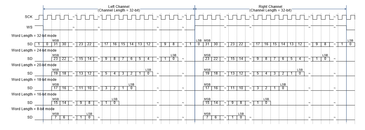
The I2S frame appears as:

This is an example for the channel length = 32. A similar case exists for the rest channel lengths, with one limitation: the word length could be less than or equal to the channel length. See the device technical reference manual (TRM) for more details.
See: the the I2S chapter of the device technical reference manual (TRM); I2S_PDL Component datasheet; CE218636 - PSOC 6 MCU INTER-IC SOUND (I2S) EXAMPLE.
| Version | Changes | Reason for Change |
|---|---|---|
| 2.40 | Removed const qualifier for the Cy_I2S_DeepSleepCallback callbackParams parameter for consistency with Cy_SysPmCallback type. | Defect fix. |
| 2.30 | Update to configure MCLK. | Update to configure i2S on core CM7. |
| 2.20 | Fixed/documented MISRA 2012 violations. | MISRA 2012 compliance. |
| 2.10.1 | Minor documentation updates. | Documentation enhancement. |
| 2.10 | Flattened the organization of the driver source code into the single source directory and the single include directory. | Driver library directory-structure simplification. |
| Added register access layer. Use register access macros instead of direct register access using dereferenced pointers. | Makes register access device-independent, so that the PDL does not need to be recompiled for each supported part number. | |
| 2.0.1 | Added Low Power Callback section | Documentation update and clarification |
| 2.0 | The slave operation is added, Left Justified and TDM modes are added | |
| 1.0 | Initial version |
API Reference | |
| Macros | |
| Functions | |
| Data Structures | |
| Enumerated Types | |