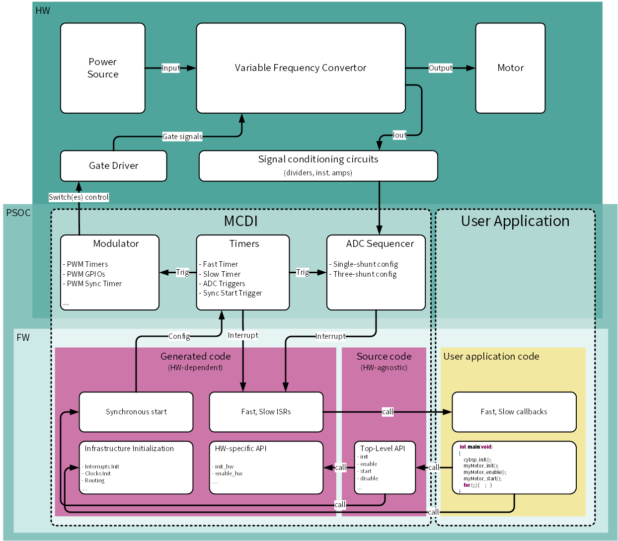
The MCDI represents the device-agnostic top-level API source code, the control service code, and the Solution Personality.
The Solution Personality:
- provides the integration with the Device Configurator
- provides a graphical configuration interface
- generates device-specific HW configuration code and the control code for the motor control applications
- generates templates for the fast and slow control loop ISRs
- supports Direct Memory Access (DMA) transfers for the ADC and Modulator data
- supports single-shunt and three-shunt load current measurement schemes
- supports up-to-two motor instances
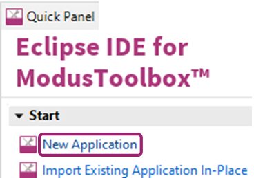
Quick Start
In order to use the MCDI as a standalone interface for alternative motor control libraries:
- Create a New Application in ModusToolbox™ IDE
-
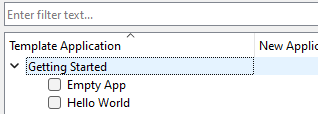
- Use the 'Empty App' template.
-
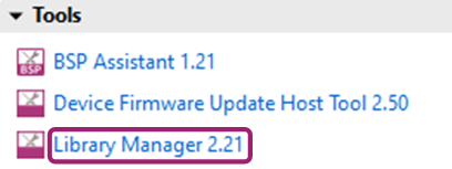
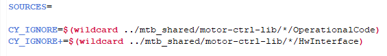
- Add the 'motor-ctrl-lib' to the created application using the Library Manager
-
- Add this code into the project 'Makefile'
-
- Launch the Device Configurator
-
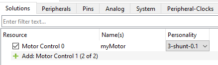
- Add the Motor Control instance
-
- Configure all hardware-specific Motor Control solution parameters and save them (or press Ctrl+S to save). After that, the appropriate code for the application will be generated by the Solution Personality.
- Add both the myMotor_slow_callback function definition and the myMotor_fast_callback function definition into the main.c.
- Build the project.
Usage Details
Assume the motor instance is named in the ModusToolbox™ Device Configurator Tool as myMotor.
Application Programming Interface
- The simplest way to use myMotor is to use the instance-based generated myMotor API:
cy_rslt_t myMotor_init(void)
Performs the Motor Control instance initialization sequence:
__STATIC_INLINE cy_rslt_t myMotor_enable(void)
Performs the Motor Control instance enable sequence:
cy_rslt_t myMotor_start(void)
Performs the Motor Control instance start sequence:
- Note
- It is not recommended to use any MCDI FW items (definitions, enums, structures or functions) from static sources or generated files which are not described in this document.
Cascade Control
- The Solution Personality GUI and its code generation engine provide users a template to create a cascaded control system with the inner and outer control loops.
The inner control loop name in MCDI is a Fast Control Loop, and the outer control loop name is a Slow Control Loop.
The Fast Control Loop settings provide:
- Automatic/manual allocation of hardware resources for Sync timer functionality
- Automatic/manual allocation of hardware resources for Fast timer functionality
- Configuration of the Fast Control Loop frequency to PWM frequency ratio
- Configuration of the time point for updating the timer compare value
- Configuration of the time point for starting ADC group conversions
- Configuration of the Fast Control Loop interrupt priority
- Definition of the Fast Control Loop callback function identifier
- The Slow Control Loop settings provide:
- Automatic/manual allocation of hardware resources for the Slow timer functionality
- Slow Control Loop frequency to Fast Control Loop frequency ratio configuration
- Slow Control Loop interrupt-priority configuration
- Slow Control Loop callback-function name definition
- The Solution Personality code generation engine declares all user-predefined callbacks as external functions with such a prototype:
extern uint16_t predefined_function_name(void)
You can use as a template (in the main.c, for example), the functions from the code snippets listed below. void myMotor_slow_callback(void)
{
(void)myMotor_VBUS_get_result();
}
void myMotor_fast_callback(void)
{
(void)myMotor_IVP_get_result();
(void)myMotor_IWP_get_result();
}
__STATIC_FORCEINLINE uint32_t myMotor_IUP_get_result(void)
Gets the ADC channel result in raw counts.
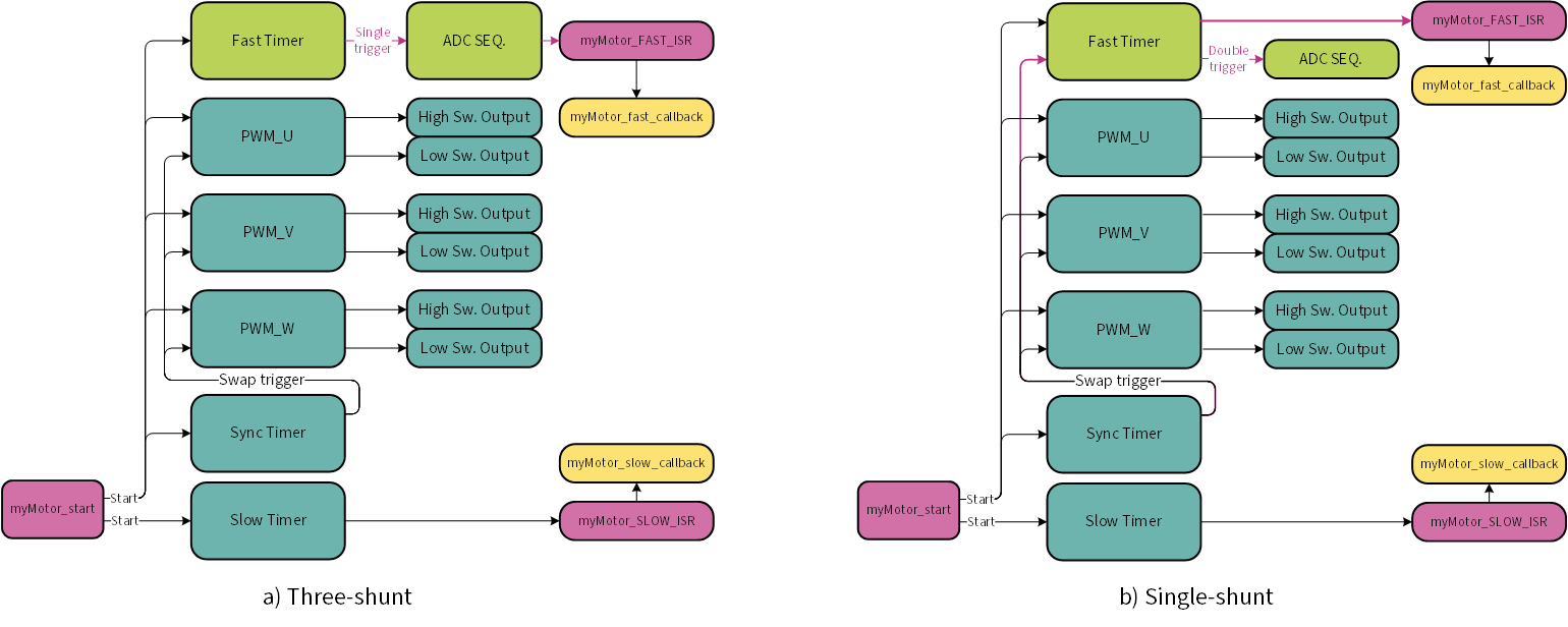
Resources interconnection and synchronization
- The MCDI Solution Personality occupies the following resources for each Motor Control instance:
- Three timers in PWM mode
- Three timers in Timer mode
- Two ADC Sequencer groups, the number of the ADC channels in each is configuration-dependent
- Seven or eight GPIOs (depends on configuration)
- Two or three HW interrupts (depends on configuration)
- The Motor Control instance resource interconnection depends on the selected measurement scheme. The difference is highlighted in the picture below.
All the PWM, Sync, Fast timers start synchronously, and the Slow timer starts asynchronously.
The instance-based myMotor_start function is provided by MCDI for this purpose.
The Fast timer generates one output pulse trigger on the compare event in the Three-shunt topology, and two output pulse triggers in the Single-shunt topology. The trigger points are configurable;
the only difference is that because of additional swap trigger used in the Single-shunt topology, the trigger points can be changed by software on the fly.
Direct Memory Access
The MCDI supports DMA transfers for the ADC and Modulator data, which enables MCU offloading and reduces the Fast ISR duration. These two features are independent and can be used simultaneously or separately.
- ADC DMA
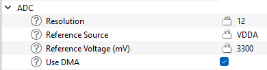
- The ADC DMA functionality is enabled by checking the "Use DMA" checkbox in the "ADC" subgroup of the MCDI configurations.
The ADC DMA transfers all conversion results of the ADC channels triggered by the Fast timer from Result registers to their respective memory locations. The ADC DMA channel is triggered automatically by the Group Done event.
- Modulator DMA
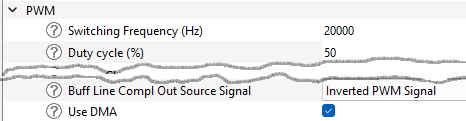
- The Modulator DMA functionality is enabled by checking the "Use DMA" checkbox in the "PWM" subgroup of the MCDI configurations.
The Modulator DMA transfers the modulator compare values from memory locations to their respective hardware Compare Buffer registers. The DMA transfer does not start automatically, to start it, the myMotor_mod_update function shall be called.
|
| | Status |
| | Statuses for the MCDI API functions.
|
| |
| | Topologies |
| | Topologies of current measurement.
|
| |
| | Data Structures |
| | Interface data structures.
|
| |
| | Functions |
| | All of the MCDI functions are instance-based; function names start with the instance name and depend on user configuration.
|
| |