Cypress PSoC 6 Bluetooth Low Energy Middleware Library 3.60
More Information

Operation Flow

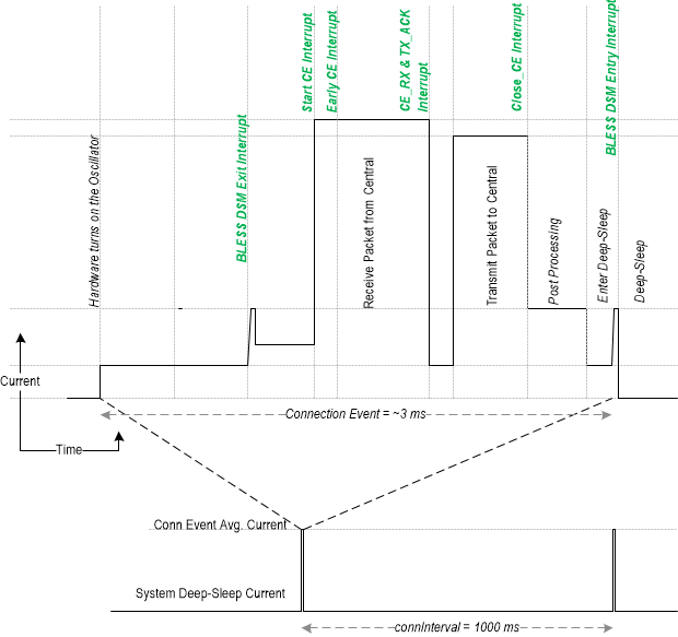
A typical application code implements three operating modes: initialization, normal operation, and low-power operation. Initialization should happen only at system power-up, or when waking from system hibernation. After initialization, the PSoC 6 BLE Middleware enters normal operation and periodically enters various degrees of low-power operation to conserve power.

System Initialization
The initialization stage happens at system power-up or when waking from system hibernation. This stage sets up the platform and the PSoC 6 BLE Middleware parameters. The application code should also start the PSoC 6 BLE Middleware and set up the callback functions for the event callbacks that happen in the other modes of operation.
System Normal Operation
Upon successful initialization of the PSoC 6 BLE Middleware or hibernate wakeup sequence, the PSoC 6 BLE Middleware enters normal mode. Normal operation first establishes a BLE connection if it is not already connected. It should then call Cy_BLE_ProcessEvents() to process all pending BLE events. When queue of BLE events is not full (Cy_BLE_GATT_GetBusyStatus() returns CY_BLE_STACK_STATE_FREE), it can transmit any data that need to be communicated and enter low-power operation, unless there is another pending event. In that case it should execute the normal operation flow again. Processing of BLE events should be performed at least once in a BLE connection event period. The BLE connection event is configured by the Central device while establishing a connection.
System Low-power Operation
When there are no pending interrupts in normal operation, the BLE Sub-System (BLESS) can be placed in low-power mode. All the high frequency blocks in BLESS are shutdown and the BLE link layer timing is maintained using low frequency clocks (WCO or PILO). CPU will not be able to access the BLESS registers in this mode. If an event happens at any time in low-power mode, it should re-enter normal operation.
Note
The MCU and BLESS have separate power modes and are able to go to different power modes independent of each other. The check marks in the following table show the possible combination of power modes of MCU and BLES
BLESS
Power Modes
MCU Power Modes
Active Sleep Deep sleep Hibernate
Active (idle/Tx/Rx) Y Y
Deep sleep (ECO off) Y Y Y
Off Y

To better understand of BLE operation flow refer Quick Start Guide section based on simple BLE example project.

Device Bonding

The PSoC 6 BLE Middleware stores the link key of a connection after pairing with the remote device. If a connection is lost and re-established, the devices use the previously stored key for the connection. The BLE stack updates the bonding data in RAM while the devices are connected. If the bonding data is to be retained during shutdown, the application can use Cy_BLE_StoreBondingData() API to write the bonding data from RAM to the dedicated flash location, as defined by the PSoC 6 BLE Middleware.

Refer to the CE215121_BLE_HID_Keyboard code example for usage details.

LFCLK Configuration for BLESS Deep Sleep Mode

The LFCLK configuration affects the PSoC 6 BLE Middleware's ability to operate in BLESS deep sleep mode. If the WCO or PILO are chosen as source clock, then the PSoC 6 BLE Middleware BLESS deep sleep mode is available for use. However, if the ILO is chosen, then the PSoC 6 BLE Middleware cannot enter BLESS deep sleep.

Note
The PSoC 6 BLE Middleware uses the LFCLK only during BLESS deep sleep mode, so ILO inaccuracy does not affect BLE communication.

Configuring PILO for BLESS Deep Sleep Mode

The PSoC 6 BLE Middleware supports using the Precision ILO (PILO) (instead of the WCO) as the LF clock source.

Using the PILO has limitations:

  • supports only a single connection
  • supports only the Peripheral/Slave role
  • not supported for preproduction hardware.

Using the PILO as the LF clock source requires:

  • configure BLE ECO (AltHF) clock in ModusToolbox Device Configurator. The recommended frequency is 16 Mhz.
  • initial trimming (call Cy_SysClk_PiloInitialTrim() function) and measuring the step size of the PILO trimming (call Cy_SysClk_PiloUpdateTrimStep function) before BLE start.

Both actions must happen during every power-up to get closest to the target frequency.

The following code snippet shows usage:

/* Perform initial PILO trimming and update the trim step size.
* \note:
* 1. Call those functions after every power-up.
* 2. Those functions require a configured BLE ECO ALTHF clock. Use ModusToolbox Device Configurator to
* configure the BLE ECO BLE ECO ALTHF clock. The recommended frequency is 16 Mhz. */
Cy_SysClk_PiloInitialTrim();
Cy_SysClk_PiloUpdateTrimStep();
/* Then configure and enable BLE Middleware, refer to Quick Start Guide section of BLE API Reference Guide */
Note
Call trimming functions Cy_SysClk_PiloInitialTrim() and Cy_SysClk_PiloUpdateTrimStep() before Cy_BLE_Start(), on the CPU core running the BLE controller.

Multi-Connection Support

The PSoC 6 BLE Middleware supports up to four simultaneous Multi-Master Multi-Slave (MMMS) BLE connections in any combination of roles. For example, it can be a master of four slave devices (4M), a master of three slave devices and a slave of another device (3M1S), or a slave of four devices (4S), or any other combination. To configure the maximum number of BLE connections, refer to the General Tab section of ModusToolbox Bluetooth Configurator Guide (Maximum number of BLE connections). The PSoC 6 BLE Middleware supports a single instance of a GATT Server (single GATT database). The number of the Server instance field is always fixed to 1 in the Bluetooth Configurator dialog. You can add additional Services or a complete Server Profile to the existing Server tree and build a GATT database. This single GATT database is reused across all BLE connections. The PSoC 6 BLE Middleware manages multiple Client Characteristic Configuration Descriptor (CCCD) values. The CCCD value for each active connection is unique.

The maximum number of CCCD storage SRAM data structures supported by the PSoC 6 BLE Middleware is determined by the number of active BLE connections/links that you select. The PSoC 6 BLE Middleware restores CCCD values in flash for each of the bonded devices while establishing a connection with a peer device.

Use the connection handle at the application level to manage the multi-connection. The connection handle (cy_stc_ble_conn_handle_t) appears when the connection is established (as the event parameter of the CY_BLE_EVT_GATT_CONNECT_IND event).

To work with a particular connection, BLE APIs (BLE Stack APIs, BLE Profile APIs) provide the parameter connHandle (e.g., Cy_BLE_BASS_SendNotification(cy_stc_ble_conn_handle_t connHandle,... ).) BLE events from the AppCallback function include a connHandle in eventParam structures to distinguish to which connection this event relates. The following code shows how an application can manage connection handles:

/* Allocate the connection handle array. Macro CY_BLE_CONN_COUNT indicates the MAX number of supported connection. */
cy_stc_ble_conn_handle_t appConnHandle[CY_BLE_CONN_COUNT] = { {.attId = CY_BLE_INVALID_CONN_HANDLE_VALUE} };
/* The callback event function to handle various events from the BLE stack */
void AppCallback1 (uint32 event, void* eventParam)
{
switch (event)
{
/*...*/
/* Add the connected device to the connection handle array */
appConnHandle[ (*(cy_stc_ble_conn_handle_t *)eventParam).attId ] =
*(cy_stc_ble_conn_handle_t *) eventParam;
break;
/* Remove the connected device from the connection handle array */
memset(&appConnHandle[(*(cy_stc_ble_conn_handle_t*)eventParam).attId],
break;
/*...*/
}
}

Loop through all connected devices:

/* Allocate the connection handle array. Macro CY_BLE_CONN_COUNT indicates the MAX number of supported connection. */
cy_stc_ble_conn_handle_t appConnHandle[CY_BLE_CONN_COUNT] = { {.attId = CY_BLE_INVALID_CONN_HANDLE_VALUE} };
/* ... */
uint32_t i;
for (i = 0; i < CY_BLE_CONN_COUNT; i++)
{
{
/* Do some action */
}
}
/* ... */

Use the Cy_BLE_GetDeviceRole(cy_stc_ble_conn_handle_t *connHandle) function to discover the role of the link-layer device connected to a peer device with the connection handle indicated by the connHandle parameter. Write attributes (characteristic, descriptors) requests from the peer device(s) for adopted services (e.g. BAS, HIDS, HRS, etc) handled by the PSoC 6 BLE Middleware.

For the Custom service, write attributes requests handled by the application level in the AppCallback () callback event function. The following code shows the handling of the Write operation by a peer device for the Custom service:

/* Call the back event function to handle various events from the BLE Stack */
void AppCallback2 (uint32 event, void* eventParam)
{
switch (event)
{
/*...*/
{
/* Store data in the database */
&writeParam->connHandle, &writeParam->handleValPair);
if(gattErr != CY_BLE_GATT_ERR_NONE)
{
/* Send an Error Response */
{
.attrHandle = writeParam->handleValPair.attrHandle,
.errorCode = gattErr
};
Cy_BLE_GATTS_SendErrorRsp(&writeParam->connHandle, &errInfo);
}
/*...*/
}
}
}

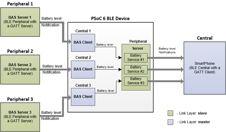
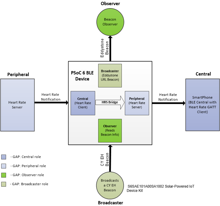
The common MMMS usage are Multi-Master Single-Slave and Multi-Role when the PSoC 6 BLE Middleware is configured in all the GAP roles (Central, Peripheral, Observer, and Broadcaster).

Multi-Master Single-Slave Usage Block Diagram

ble_multi_master_single_slave_usage_block_diagram.png

Multi-Role Usage Block Diagram

ble_multi_role_usage_block_diagram.png

Refer to code examples CE215118_BLE_Multi_Master_Single_Slave and CE215555_BLE_Multi_Role for more details.

BLE Interrupt Notification Callback

The PSoC 6 BLE Middleware exposes BLE interrupt notifications to the application which indicates a different link layer and radio state transitions to the user from the BLESS interrupt context. The user registers for a particular type of a callback and the PSoC 6 BLE Middleware will call that registered callback basing on the registered mask (Refer to the Cy_BLE_RegisterInterruptCallback() and Cy_BLE_UnRegisterInterruptCallback() APIs). All interrupts masks are specified in the cy_en_ble_interrupt_callback_feature_t enumeration.

The possible interrupts which can trigger a user callback:

  1. CY_BLE_INTR_CALLBACK_BLESS_STACK_ISR - Executed on every trigger of the BLESS interrupt.
  2. CY_BLE_INTR_CALLBACK_BLESS_INTR_STAT_DSM_EXITED - Executed when the BLESS exits BLESS deep sleep mode and enters BLESS active mode. A BLESS deep sleep exit can be triggered automatically by link layer hardware or by different PSoC 6 BLE Middleware data transfer APIs, which needs the BLESS to be active.
  3. CY_BLE_INTR_CALLBACK_BLELL_CONN_EXT_INTR_EARLY - Executed when the BLESS connection engine in Slave mode detects a BLE packet that matches its access address.
  4. CY_BLE_INTR_CALLBACK_BLELL_CONN_INTR_CE_RX - Executed when the BLESS connection engine receives a non-empty packet from the peer device
  5. CY_BLE_INTR_CALLBACK_BLELL_CONN_INTR_CE_TX_ACK - Executed when the BLESS connection engine receives an ACK packet from the peer device for the previously transmitted packet.
  6. CY_BLE_INTR_CALLBACK_BLELL_CONN_INTR_CLOSE_CE - Executed when the BLESS connection engine closes the connection event. This interrupt is executed on every connection interval for connection, irrespective of data tx/rx state.
  7. CY_BLE_INTR_CALLBACK_BLESS_INTR_STAT_DSM_ENTERED - Executed when the BLESS enters deep sleep mode. A user call to the Cy_SysPm_DeepSleep() function will trigger the BLESS deep sleep entry sequence. A time instance when each of these interrupts (#1 to #7) are triggered in a connection event are shown below (green).
  8. CY_BLE_INTR_CALLBACK_BLELL_SCAN_INTR_ADV_RX - Executed when the BLESS scan engine receives an advertisement packet from the peer device.
  9. CY_BLE_INTR_CALLBACK_BLELL_SCAN_INTR_SCAN_RSP_RX - Executed when the BLESS scan engine receives a scan response packet from the peer device in response to a scan request from the scanner.
  10. CY_BLE_INTR_CALLBACK_BLELL_ADV_INTR_CONN_REQ_RX - Executed when the BLESS advertisement engine receives a connection request from the peer central device.

An application can use these interrupt callbacks to know when the RF activity is about to begin/end or when the BLE device changes its state from advertisement to connected, or when the BLESS transitions between active and low-power modes, etc. These BLESS real-time states can be used to synchronize an application with the BLESS or prevent radio interference with other peripherals etc.

ble_intr_notify_feature.png

To register / un-register a callback following APIs are available: Cy_BLE_RegisterInterruptCallback() and Cy_BLE_UnRegisterInterruptCallback().

Unsupported Features

The PSoC 6 BLE Middleware stack does not support the following optional Bluetooth v5.0 protocol features, as listed in Vol 6, Part B, section 4.6 of the specification:

  • Connection Parameters Request Procedure (Vol 6, Part B, section 4.6.2)
  • Extended Reject Indication (Vol 6, Part B, section 4.6.3)
  • Slave-initiated Features Exchange (Vol 6, Part B, section 4.6.4)
  • Stable Modulation Index - Transmitter (Vol 6, Part B, section 4.6.10)
  • Stable Modulation Index - Receiver (Vol 6, Part B, section 4.6.11)
  • LE Extended Advertising (Vol 6, Part B, section 4.6.12)
  • LE Periodic Advertising (Vol 6, Part B, section 4.6.13)
  • Channel Selection Algorithm #2 (Vol 6, Part B, section 4.6.14)
  • Minimum Number of Used Channels Procedure (Vol 6, Part B, section 4.6.15)

Low-power Modes

The PSoC 6 BLE Middleware automatically registers sleep and deep sleep callback functions. These functions request the BLE Stack to put Bluetooth Low Energy Sub-System (BLESS) to low-power mode.

External PA/LNA Support

RF front ends come in a variety of combinations. The most popular and comprehensive RF front ends come with a built-in power amplifier (PA) in the transmit path, a low-noise amplifier (LNA) in the receive path, a transmit/receive bypass path to bypass both the PA and LNA, and RF switches to select between transmit, receive, and bypass paths. Some front ends support multiple antennas. Some front ends have a built-in low-pass filter after the power amplifier. The discrete front ends also have almost the same configuration.

ble_ext_pa_lna_control.png
Chip Enable Signal
This signal is needed to put the front end to sleep or in standby whenever there is no radio activity. The signal is ON when either PA control or LNA control is ON.
Tx ENABLE
This signal is turned ON during transmission and turned OFF when not transmitting. This signal is active a little earlier than the actual start of transmission to allow for the time it takes for the Power amplifier to ramp up. This delay can be set in the EXT_PA_LNA_DLY_CNFG register.
Rx ENABLE
This signal is needed to choose between the bypass path and the LNA path. This signal is ON during reception and OFF when the receiver is OFF. This output is visible if the Enable external LNA Rx control output parameter is selected on the Advanced tab.

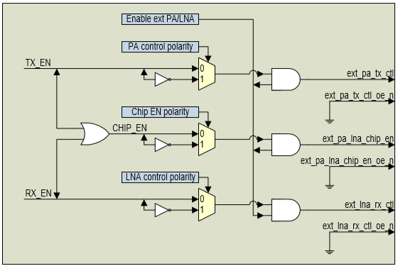
The polarity of these signals are configurable and can be set in the EXT_PA_LNA_CTRL register by Cy_BLE_ConfigureExtPA() API.

Additional Resources

For more information, refer to the following documents:

ModusToolbox Software Environment, Quick Start Guide, Documentation, and Videos
PSoC 6 BLE Middleware Code Examples at GITHUB
ModusToolbox BT Configurator Tool Guide
ModusToolbox Device Configurator Tool Guide
PSoC 6 BLE Middleware API Reference Guide
AN210781 - Getting Started with PSoC 6 MCU with Bluetooth Low, Energy, (BLE) Connectivity
PDL API Reference
PSoC 6 Technical Reference Manual
CySmart - BLE Test and Debug Tool
CY8CKIT-062-BLE PSoC 6 BLE Pioneer Kit
Cypress Semiconductor

Note
The links to another software component's documentation (middleware and PDL) point to GitHub to the latest available version of the software. To get documentation of the specified version, download from GitHub and unzip the component archive. The documentation is available in the docs folder.